Chapter 10. PCI CARD – Specifications
- 10.1. Pin-outs and electrical characteristics
- 10.2. Mechanical dimensions
- 10.3. Connecting servo modules
- 10.4. Axis interface modules
-
- 10.4.1. Typical servo configurations
-
- 10.4.1.1. Analogue system with encoder feedback
- 10.4.1.2. Incremental digital system with encoder feedback and differential output
- 10.4.1.3. Incremental digital system with encoder feedback and TTL output
- 10.4.1.4. Incremental digital system with differential output
- 10.4.1.5. Incremental digital system with TTL output
- 10.4.1.6. Absolute digital (CAN based) system
- 10.4.1.7. Absolute digital (CAN based) system with conventional (A/B/I) encoder feedback
- 10.4.2. AXIS – Optical Isolator
- 10.4.3. AXIS – DAC (Digital-to-Analogue Converter)
- 10.4.4. AXIS – Differential breakout
- 10.4.5. AXIS – Breakout
This chapter describes all connectors, pins and the electrical characteristics of the PCI card.
10.1. Pin-outs and electrical characteristics
10.1.1. RS485: Extension modules
10.1.2. GPIO connectors
Each pin can be configured as digital input or output.
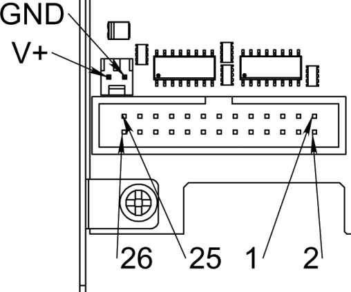
10.1.2.1. Pinout
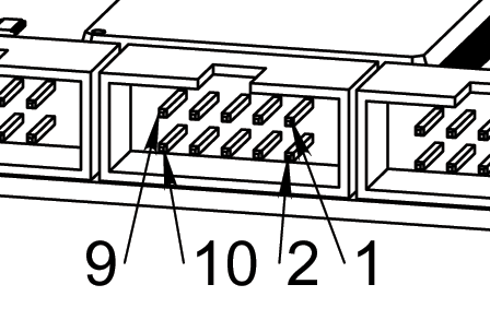
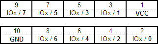
Figure 10-4. Pin numbering of GPIO connectorsFigure 10-5. Pinout of GPIO connectors
10.1.2.2. Input electrical characteristics
These are simple non-isolated I/O ports for general purpose usage. All voltage levels are referenced to the PC ground. It is not recommended to directly connect signals which can exceed the absolute maximum ratings.
Absolute maximum ratings
Maximum input voltage: 3.3Volts
Minimum input voltage: 0Volts.
Maximum current of the 4x8 output100mA
Logic levels
Minimum high-level input voltage: 2Volts
Maximum low-level input voltage:0.8Volts
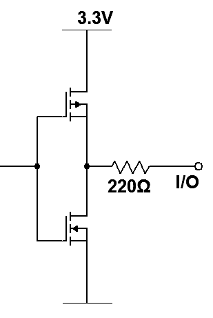
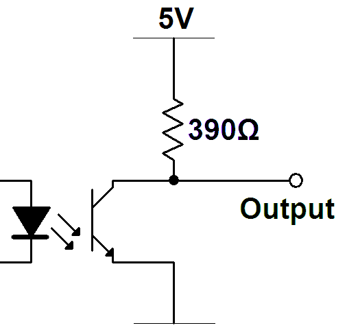
10.1.2.3. Output electrical characteristics
The totem pole outputs are short circuit protected by a series resistor, see figure:

Output logic levels (unloaded)
Minimum high-level output voltage: 2.9Volts
Maximum low-level output voltage:0.4Volts
10.1.3. CAN-bus: Position reference for servo modules
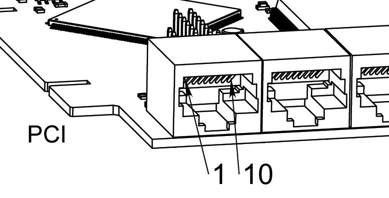
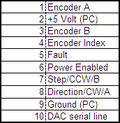
10.1.4. Axis connectors
All voltage levels on the axis connectors are referenced to the PC ground. It is recommended to use axis modules to connect the servo amplifier modules to the PCI card. See chapter 3.
10.1.4.1. Encoder input characteristics
Absolute maximum ratings
Maximum input voltage: 3.3Volts
Minimum input voltage: 0Volts.
Logic levels
Minimum high-level input voltage: 2Volts
Maximum low-level input voltage:0.8Volts
10.1.4.2. Fault inputs
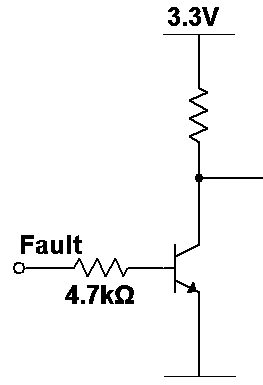
Logic levels
Minimum high-level input voltage: 1.5Volts
Maximum low-level input voltage:0.5Volts
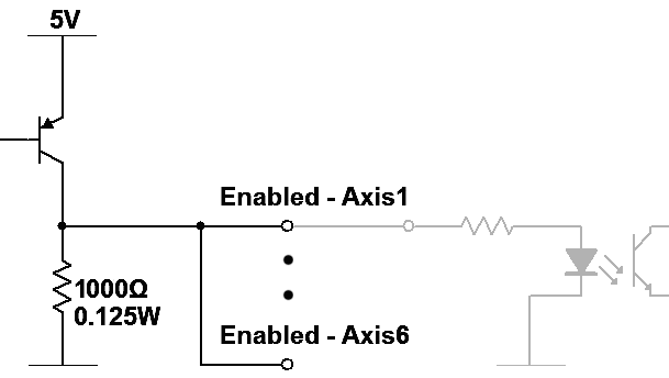
10.1.4.3. Enabled outputs
The enable output is common for all axes.
Maximum output source current:100mA
10.1.4.4. Step, Direction and DAC serial line output characteristics
The totem pole outputs are short circuit protected by a series resistor, see figure.
Output logic levels (unloaded)
Minimum high-level output voltage: 2.9Volts
Maximum low-level output voltage:0.4Volts
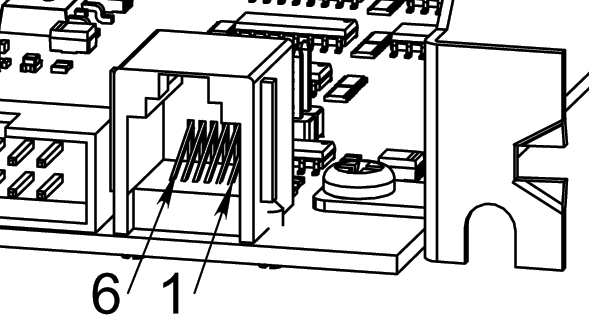
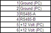
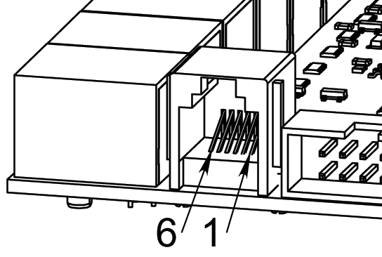
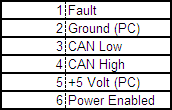
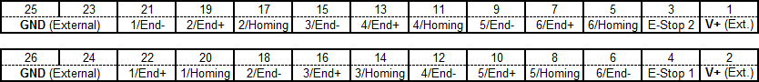
10.1.5. Homing & end switch connector
10.1.5.1. Pinout
10.1.5.2. Input electrical characteristics
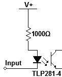
Mechanical switch or open collector output can be connected between input pins and the external ground (GND).
Logic levels referred to voltage drop between V+ , Input pins and current consumption
Minimum high-level voltage drop: 5VoltsIF3.9mA
Maximum recommended high-level voltage drop:12VoltsIF11mA
Maximum low-level voltage drop:1Volts
Absolute maximum ratings
Forward voltage drop between V+ and Input pins:30Volts
Forward current along V+ and Input pins:30mA
Reverse voltage drop between V+ and Input pins:5Volts
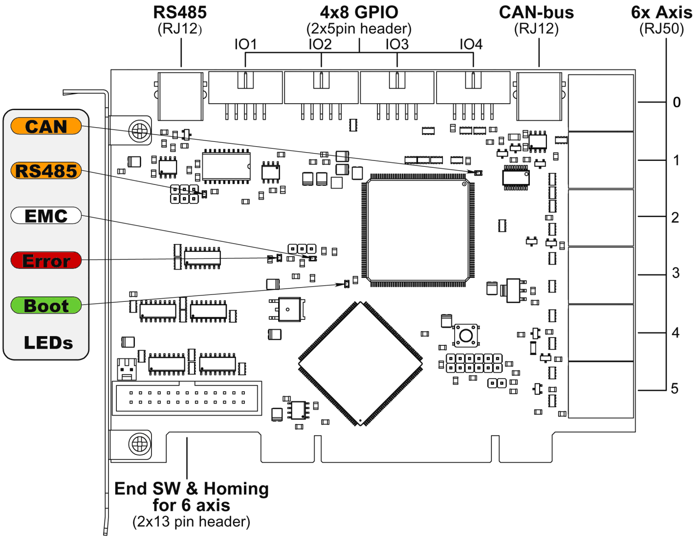
10.1.6. LEDs
10.1.6.1. CAN
Color: Orange
Blink, during data communication.
On, when any of the buffers are full – communication error.
Off, when there isn’t data communication.
10.1.6.2. RS485
Color: Orange
Blink, during initialization of modules on the bus
On, when the data communication is active between all initialized modules.
Off, when any of the initialized modules dropped off because of an error.
10.1.6.3. EMC
Color: White
Blink, when LinuxCNC is running.
Otherwise off.
10.1.6.4. Boot
Color: Green
On, when system booted successfully.
Otherwise off.
10.1.6.5. Error
Color: Red
Off, when there is no fault in the system.
Blink, when there is a PCI communication error.
On, when watchdog timer overflowed.
10.2. Mechanical dimensions
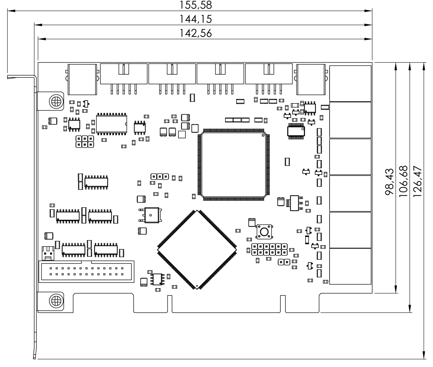
All dimensions are given in mm. Not shown dimensions are compliant with PCI specification and standard.
10.3. Connecting servo modules
This chapter is about how to connect servo modules to the PCI motion control card for driving a machine.
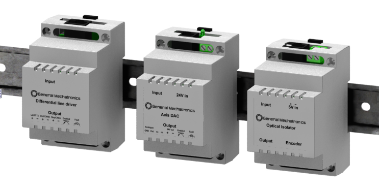
10.4. Axis interface modules
Small sized DIN rail mounted interface modules represent an easy way to connect different types of servo modules to the axis connectors. First in this chapter, seven different system configurations are presented that can be set up to evaluate typical applications. Then the detailed description of the four available interface modules is presented.
10.4.1. Typical servo configurations
In order to evaluate the appropriate servo-drive structure the modules have to be connected as it is shown in the following block diagrams. All the modular cables (RJ50 and RJ45) have to be straight wired.
10.4.1.1. Analogue system with encoder feedback
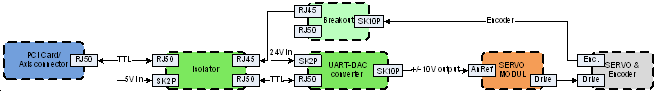
This configuration can be used to interface with the conventional analogue servo modules which have voltage level reference signal input.
10.4.1.2. Incremental digital system with encoder feedback and differential output
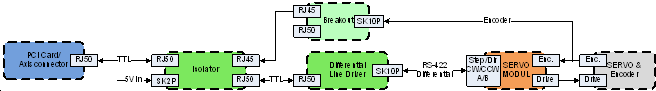
This configuration can be used to interface with three types of incremental servo modules with the following differential reference inputs: Step/Direction, Clockwise/Counter clockwise and Quadrant A/B. It is possible to read the servo position in the PC with the encoder feedback connection.
10.4.1.3. Incremental digital system with encoder feedback and TTL output
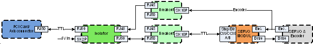
This configuration can be used to interface with three types of incremental servo modules with the following TTL level reference inputs: Step/Direction, Clockwise/Counter clockwise and Quadrant A/B. It is possible to read the servo position in the PC with the encoder feedback connection.
10.4.1.4. Incremental digital system with differential output

Same configuration as in chapter 3.1.1.2. but without isolation and encoder feedback. This configuration is recommended when the servo module has optically isolated inputs.
10.4.1.5. Incremental digital system with TTL output

Same configuration as in chapter 3.1.1.3. but without isolation and encoder feedback.
10.4.1.6. Absolute digital (CAN based) system
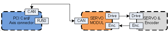
Servo modules are connected along the CAN bus interface.
10.4.1.7. Absolute digital (CAN based) system with conventional (A/B/I) encoder feedback
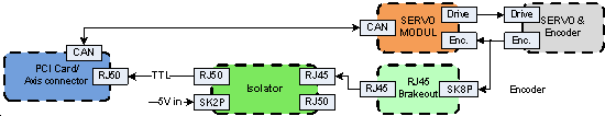
Servo modules are connected along the CAN bus interface, expanded with conventional encoder feedback along an optical isolator to the RJ50 axis connector.
10.4.2. AXIS – Optical Isolator
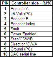
This module can be used to isolate all the signals referred to the PC ground, and to interface with TTL or differential output encoders. The controller side of the module can be connected to the PCI card’s Axis connector. The machine side reference output can be connected to an AXIS – Breakout module or to an AXIS – Differential breakout module, or can be hard wired directly to TTL inputs of a servo controller.

Pinout – Controller side
Pinout – Machine side
10.4.2.1.
Electrical characteristics
Output characteristics of pins on reference output (RJ50) connector:
All output pins are TTL compatible.
Maximum output high-level voltage:5Voltsno load
Minimum output high-level voltage:2VoltsIL7.5mA
Maximum output low-level voltage:0.1Volt
Input characteristics of fault input pin on reference output (machine side RJ50) connector:
Minimum input high-level voltage:2VoltsIF3.85mA
Maximum input low-level voltage:1Volts
Absolute maximum input voltage:7VoltsIF27mA
Input characteristics of pins on encoder input (RJ45) connector:
DC characteristics for differential output encoder:
Minimum high-level input voltage difference:0.2Volt
Minimum low-level input voltage difference:-0.2Volt
Maximum differential input voltage:6Volts
DC characteristics for TTL output encoder: The negative differential inputs must be left open. The outputs have to be connected to the positive inputs.
Minimum input high-level voltage:2VoltsIH110A
Maximum input low-level voltage:1.2Volts IL-110A
Maximum frequency at symmetrical square signal:500kHz
Maximum load current of encoder power:500mA
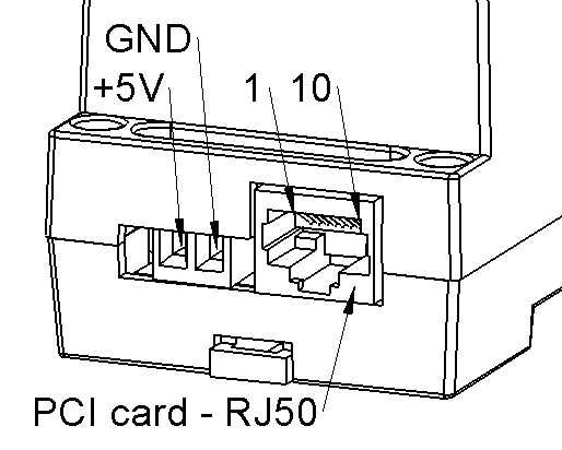
Input DC characteristics of pins on PCI card – RJ50 (controller side) connector:
Minimum input high-level voltage:2VoltsIF3.85mA
Maximum input low-level voltage:1Volts
Absolute maximum input voltage:7VoltsIF27mA
Output DC characteristics of Fault output pin on PCI card – RJ50 (controller side) connector:
Maximum output high-level voltage:5Voltsno load
Minimum output high-level voltage:2VoltsIL7.5mA
Maximum output low-level voltage:0.8VoltIL-360A
Supply voltage:
Recommended supply voltage:5Volts
Absolute maximum supply voltage:5.5Volts
Absolute minimum supply voltage:4.5Volts
Maximum current consumption without encoder:200mA
Maximum current consumption with encoder:750mA
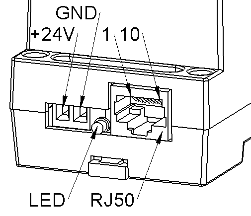
10.4.3. AXIS – DAC (Digital-to-Analogue Converter)
This module converts the digital signal of the PCI card to analogue output to drive a speed or current mode servo amplifier. The isolator module is recommended in most cases to be used with this module, see chapter 3.1.1.1. “Analogue system with encoder feedback”.

The controller side RJ50 connector of this module has to be connected to the machine side of an AXIS – Optical Isolator module or directly to the PCI card (when the servo amplifier is isolated). The machine side terminal output can be connected to an analogue type servo amplifier.
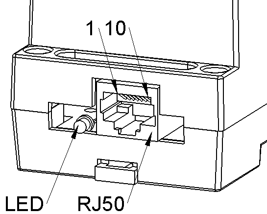
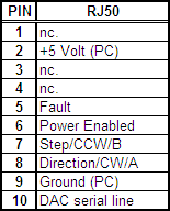
Controller side pinout
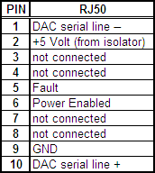
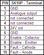
Machine side pinout

Electrical characteristics
Controller side RJ50 connector:
Serial line in single line connection – only serial line+ is connected (most cases):
Serial line+ minimum high level input voltage:3Volts
Serial line+ maximum low level input voltage:2Volts
Serial line in differential connection:
Minimum high level input voltage difference:0.4Volts
Maximum low level input voltage difference:0.4Volts
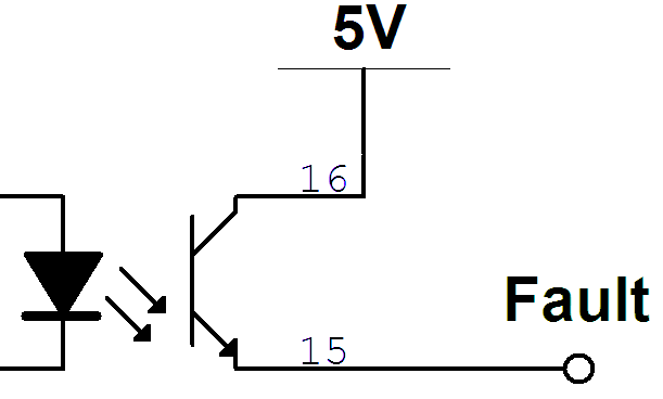
Fault signal – open emitter output signal:
Maximum high level output voltage:5Volts
Enabled input signal
Minimum high level input voltage:2Volts
Maximum low level input voltage:0.8Volts
Machine side terminal connector:
DAC output:
Maximum output voltage:10Volts
Minimum output voltage:-10Volts
Output voltage level accuracy:1%
24V output:
Maximum output load current:200mA
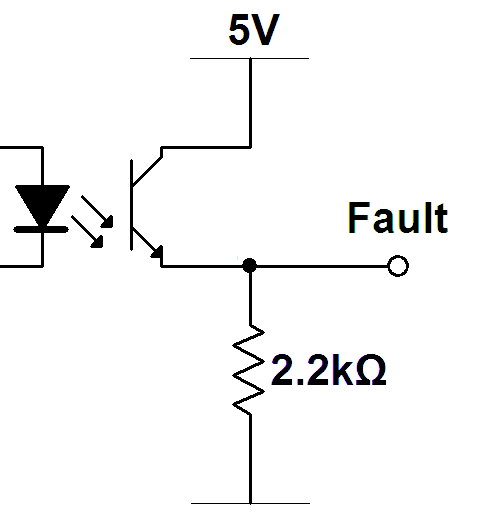
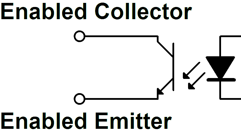
Enabled output signal:
Collector-emitter breakdown voltage:80VoltsIC0.5mA
Emitter-collector breakdown voltage:7VoltsIE0.1mA
Maximum collector dark current:0.1AVCE48Volts

For more information please refer to Toshiba TLP281 optocoupler’s datasheet.
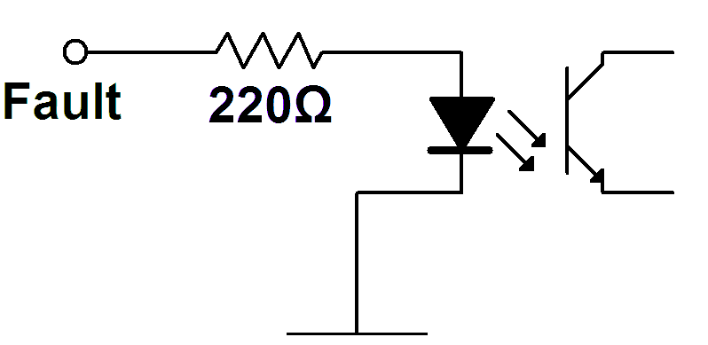
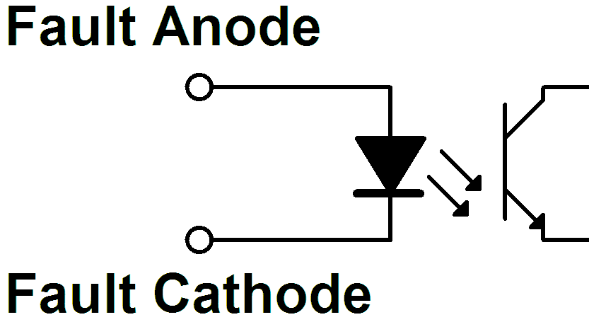
Fault input signal - LED:
LED forward voltage:1.15VoltsIF10mA
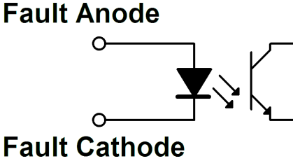
For more information please refer to Toshiba TLP281 optocoupler’s datasheet.
Operating conditions
The following conditions have to be fulfilled to have the analogue voltage level and enabled signal at the output in order to drive the analogue servo module:
External 24 Volt DC supply is connected and the digital part is supplied with 5 Volts from the isolator or from the PCI card.
No watchdog error
No DAC voltage level fault
The valid digital reference signal comes on UART from the PC
No servo fault - The fault signal from the servo module is LOW
Drive enabled - Enabled signal from the PC is HIGH
Fault conditions
The following flowchart describes the fault handling of the axis DAC module:
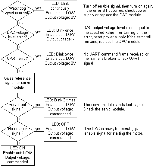
Watchdog reset occurred:
- LED blinks continuously
- The fault signal from the servo module is overdriven to HIGH
- The Enabled signal to the servo module is overdriven to LOW
- The analogue output is equal to 0 Volt.
- Reversed when enable signal from PC is turned off and then turned on again, or power reset occurred.
DAC output voltage level is not equal to the specified voltage (DAC error):
- LED blinks once every second
- The fault signal from the servo module is overdriven to HIGH
- The Enabled signal to the servo module is overdriven to LOW
- The analogue output is equal to 0 Volt.
- Reversed on power reset. If the error still remains, replace the DAC module.
No digital input or the UART frame is broken:
- LED blinks twice every second
- The fault signal from the servo module is overdriven to HIGH
- The Enabled signal to the servo module is overdriven to LOW
- The analogue output is equal to 0 Volt.
- Reversed when digital input signal on UART line becomes valid again.
Fault signal from servo module is HIGH:
- LED blinks tree times every second
- The analogue output is equal to 0 Volt.
- Reversed when fault signal becomes LOW again.
Enabled signal from PC is LOW:
- LED is off.
- The analogue output is equal to 0 Volt.
- Reversed when enabled signal becomes HIGH again.
10.4.4. AXIS – Differential breakout
This module can be used to interface with servo modules which have differential reference input.

The controller side can be connected directly to the PCI card’s axis connector if there is no need for optical isolation or encoder feedback to the controller. In any other cases the controller side should be connected to the machine side RJ50 connector of an AXIS – Optical Isolator module.
Controller side pinout
Machine side pinout
Electrical characteristics
Controller side RJ50 connector:
TTL inputs (pins: 6, 7, 8, 10):
Minimum high level input voltage:2Volts
Maximum low level input voltage:0.8Volts
For more information please refer to AM26LS31 differential line driver’s datasheet.
Machine side terminal connector:
Differential outputs:
Maximum low level output current:20mA
Maximum high level output current:-20mA
For more information please refer to AM26LS31 differential line driver’s datasheet.
Enabled output signal:
Collector-emitter breakdown voltage:80VoltsIC0.5mA
Emitter-collector breakdown voltage:7VoltsIE0.1mA
Maximum collector dark current:0.1AVCE48Volts
For more information please refer to Toshiba TLP281 optocoupler’s datasheet.
Fault input signal - LED:
LED forward voltage:1.15VoltsIF10mA
For more information please refer to Toshiba TLP281 optocoupler’s datasheet.
10.4.5. AXIS – Breakout
This module can be used for wiring out the reference outputs or the encoder inputs modular contacts to a simple terminal connector. In case of the encoder it can be useful to split the signals between the servo module and the encoder feedback to the PC.
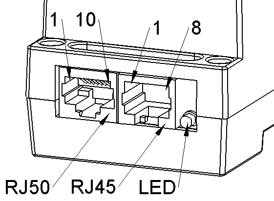
Connectors
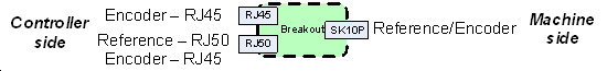
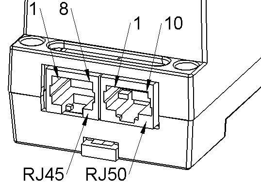
Controller side RJ50 & RJ45 modular connectors
The 10-pin RJ50 connector can also host 8-pin RJ45 plug. In case of splitting the encoder signals, two RJ45 encoder cables can be used.
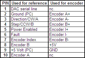
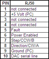
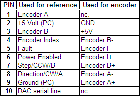
Controller side RJ50 – Reference or Encoder pinout:
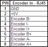
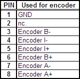
Controller side RJ45 – Encoder pinout:
The power supply of the encoder is not connected on the secondary (RJ45) connector to ensure that the encoder sensor gets the supply voltage from one source only.
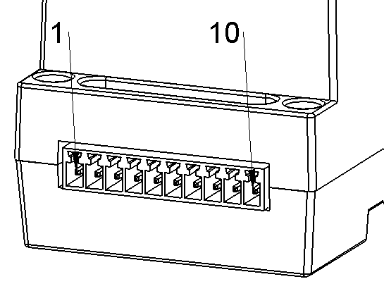
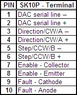
Machine side SK10P - Terminal connector pinout: