Chapter VI. Aim-specific applications
VI.1. SOC (System On a Chip)
VI.1.1. What is SOC?
The abbreviation "SOC” stands for "System on a Chip”, that is a system in an integrated circuit case. When it was being designed, the important factors to be taken into consideration were the low total cost, the small size and consumption of the unit. There is no equivocal boundary between SOCs and microcontrollers. Generally, we mean by a SOC a device having more than 128 kb of RAM, and by a microcontroller a device having less than that. Of course, this boundary is not evident since there are devices with more than 512k of memory manufactured as micorcontrollers. There is another difference between the two (but this is not always true either): on a SOC, an interactive operating system is run (in most cases a Unix-clone, e.g. Linux), whereas a task-specific program runs on a microcontroller. This aspect has a relationship with memory size: in general, a Unix-clone needs more than 128 kb of memory.
VI.1.2. Parts of a SOC
A SOC (or microcontroller) can be composed of different hardware elements but it always contains one or more CPU (or eventually DSP) cores, which is an operation processing unit. Traditionally, a manufacturer of a SOC integrate into the SOC a core CPU from another manufacturer and then it surrounds that core with its own hardware elements and then it encases the whole into a case. This part corresponds approximatively to the processor of PCs. There are always power supply and bus controller circuits, too. The pins of these elements (e.g. those of the CPU core) do not figure directly among the pins of the SOC. Its buses are generally internal buses, if there is a possibility to connect it to an external memory/peripheral device, it is made through a bus adapter.
Optional, traditional hardware elements:
-
RAM: operative memory. In the case of microcontrollers, the small-sized memory is placed in the case, whereas in the case of SOCs, there is a memory bus output to which an external, in general a dynamic RAM can be attached to the SOC. In the case of the latter solution, system designers can decide about the size of the memory necessary for their systems. Microcontrollers are manufactured with different memory sizes in order that the one that is the most suitable and most economic for a given application could be bought.
-
ROM: read-only memory. In microcontrollers, the ROM stores the whole program and is placed in the case; whereas, in a SOC, there is an external ROM bus and it contains either the whole operating system or only a bootloader and the real operating system is loaded from elsewhere (storing device or network). Nowadays, SOCs and microcontrollers are provided with a flash EEPROM in order that their software (firmware) could be replaced by their users. It is a really comfortable solution for software development: correcting a program error, in the era of EPPROMs could be deleted by UV-light, took at least 10 minutes because of deleting, but nowadays it takes some milliseconds. A SOC/microcontroller may contain a code that is able to program its own ROM memory (self-write, bootloader). When a program ready to be used and a big quantity of microcontroller is ordered, the manufacturers produce microcontrollers with a mask-programmed ROM, when the unchanged program is written in the ROM already during manufacturing, so they have the lowest unit cost.
-
Oscillator: the smaller microcontrollers contain an internal RC oscillator, which fulfils the role of clock signal generators. The produced frequency is not precise enough for USB and Ethernet but is sufficient for RS-232.
-
Watchdog: is a counter independent of CPU, which has to be reset periodically from the program. In case the program “hangs up” (or does not reset it), the watchdog in case of overflow sends a hardware reset signal to the CPU , that is a hardware restart takes place.
-
Interrupt and DMA controllers: control interrupts and data movement in the direct memory. All peripheral devices (timers, A/D converters, GPIO) are able to ask for an interrupt under certain conditions, after which interrupt handlers start to run.
-
A GPIO is a free to use digital input/output.. In general it has a parallel port interface, that is the number of wires corresponds to the length of a word of the processor and these wires can be updated and read with one statement. All SOCs have a GPIO in order that designer of the system could be able to signal the operational status of the device with the help of peripheral devices (e.g. with a LED). A GPIO can be programmed for both the input and the output: a code portion tells it whether the pin gets the value of the ouput register (so reading this we will get the value of the output register) or the content of the bit can be set in a high impedance state (TRI-State) from the outside, from an input (e.g. from a button).
-
A/D converter: analog voltage can be connected to the given pin, which can be read from the program. Integrated converters are of 10-12 bits, and their conversion clock signal is of some megahertz. More pins can constitute an analog input to the converter. In that case, the channel intended to be used has to be chosen with a multiplexer. The reference voltage of an A/D converter may be the power supply voltage of the controller, a pin able to receive analog input or an internal, programmable voltage reference.
-
Comparator: pins used for analog input can be connected to a comparator circuit, on the other input of which one can choose between the same possibilities as in the case of A/D converters. The output of a comparator is the result of comparison of the two signals (smaller than, greater than or equal to).
-
Timer/Counter: These devices contain an incremental counter. When a timer reaches a given value, it gives an output signal or requests an interrupt. The input of counters may be a digital input pin or the signal of the system clock after a prescaler. When the counter overflows, it requests an interrupt. The value of the counter can be read. In general, 8- or 16-bit counters are used, the other bits have to be realized in the interrupt handler, from software.
-
PWM output: pulse-width modulated output. A square wave of a given frequency (output of a timer) the fill factor of which can be programmed (at 0% it is only Low level, at 100% it is only High level). It can be used to regulate the performance of DC motors and lamps in a low-loss way. In general, there are two of them in order that the complete H-bridge could be realized (with two other digital outputs to regulate the direction of rotation). There is no integrated power level controller, external FETs have to be adapted to them.
-
Serial input/output: two-wired asynchronous communication, easy to be realized even in machine code. One could connect to serial ports (COM) of older PCs. These ports have disappeared from PCs by now but they are still in use in industry because of their simplicity and robustness. The power supply voltages of a SOC (and a microcontroller) do not make possible the signal levels that comply with RS-232 standards so an external level adapter should always be used. Similarly, the system can be adapted to RS-422 if a transmission of a long distance is needed. The data transfer rate can range from 75 bit/sec (baud) to 115200 bit/sec. Ordinary speed is between 9600 and 19200 bit/sec. Connection to modern PCs can be carried out by a serial extension card or an USB-serial converter, which create a virtual serial port on the PC. In the case of SOCs (on which an operating system runs), console messages are often directed to the serial port, starting from launching the kernel. The header of the serial port plug is led out on the integrated circuit plate containing the SOC, without level adapting. With a level adapter and a terminal program running on a PC, commands can be given directly to the operating system.
-
USB: nowadays, nearly all computers contain USB ports and many USB-devices are avaliable. The advantages of USB: gives power supply (5V/500mA), data transmission speed is bigger than that of a serial port: 1.5 Mbit/sec (1.0 low speed), 12 Mbit/sec (1.0 full speed), 480 Mbit/sec (2.0 high speed), 5 Gbit/sec (3.0 superspeed) and that it can be plugged into the PC any time, which runs its driver automatically. USB communication can be realized in many ways: PC may be the master and SOC the USB peripheral devices, or a SOC may be the master (USB Host) and a USB-stick or an external HDD, webcam may be the peripheral device. The way how a peripheral device is realized by a SOC can also be various: in general, they use one of the levels of the USB stack, for example CDC, which is detected as a serial port in the PC, therefore it can even communicate with programs that are able to handle serial ports without any drivers or program library. Communication can also be realized with a HID (human interface device) protocol and open-source libusb. In the latter cases, the necessary programs have to be installed on the PC.
-
Ethernet: local network with a speed of 10/100/1000 Mbit/sec. In general, it is not integrated in a SOC because it requires an external transformer and transceiver but a SOC should be prepared to handle that with a MII port of the necessary bandwidth. A SOC equipped with Ethernet is generally not managed with native Ethernet protocol but with TCP/IP. Therefore a SOC can be connected to the Internet, so there will not be any problems with distance in communication. Above the TCP/IP level, there may be applications with standard output: for example a web server. In the latter case, communication can be established with a SOC through a web browser on the PC (or on a cellphone). A SOC may typically be used as a wide-band router, which contains an Ethernet port for Internet connection (a DHCP or PPPoE client, logged in a service provider, run on that port) and a 4-port Ethernet switch. Through these ports, DHCP and other servers provide the connection of the computers. Configuring takes place on a web interface, with the help of an integrated web server. The operating system is generally Linux, the EEPROM and the RAM are external. A serial port is integrated on the printed circuit board, that is where kernel messages are sent to. In some devices, there is also an USB port. Peripheral devices connected to that port (printer, external HDD) can be seen by the devices of the network.
-
I2C: two-wired (SDA – serial data line, SCL – serial clock line) serial communication developed by Philips, where more slave devices can be connected to a master device, thanks to the open collector outputs and pull-up resistors. A SOC is able to function both as a master and as a slave but it is most frequently used as a master. With I2C, different peripheral devices can be connected to a SOC: for example an EEPROM, a thermometer, an accelerometer, a volume control, a tv-tuner. The speed of the clock signal of I2C is max. 100 kHz, and 400 kHz in the case of newer devices. Each device has a 7-bit address, therefore 127 devices can be used on the bus. Intel applies this protocol on some of its motherboards, under the name smbus. Communication is always initiated by the master, and at the end of this, the addressed device sends an acknowledge ("ACK”) signal, so its presence can be detected.
-
SPI: serial peripheral interface. The SPI bus uses two data lines: one from the master to the slave, the other in the opposite direction, therefore communication may be full duplex. There is only one clock signal: from the master to the slave. It was designed as a point-to-point connection but more slaves can be connected to the bus with the help of the "Slave Select” signal, and among slaves only one has to be activated. The standards do not mention a maximal speed; information can be obtained from the technical specifications sheet of the given manufacturer. However, this speed is in the order of Mbit/seconds, which is more than at I2C.
-
RTCC: real-time clock with a separate source of power. System time is updated even after SOC is turned off.
-
CAN bus interface: hardware and software protocol mainly used in automotive industry, for the communication between the central computer (ECU or eventually a SOC) and sensors and actuators. Some industrial and health care devices also use that.
-
Video display device: SOCs, integrated in media players, contain an mpeg-2 and h.264 video decoder, nowadays with a HDMI output.
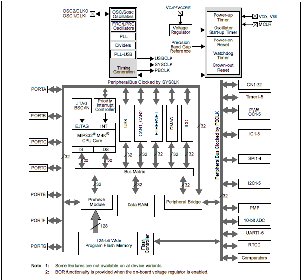
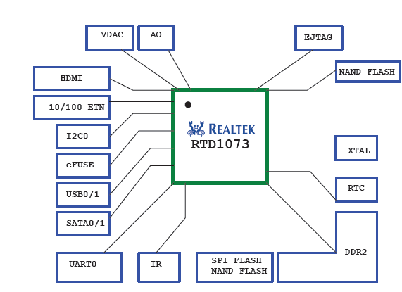
Now let's see two typical block diagrams: that of an omniscient microcontroller (source: Microchip, type: PIC32MX family), and that of a SOC designed for a media player device (source: Realtek, type: RTD1073) Realtek is less documented, because there only the external connections were mentioned.
VI.2. Embedded devices, development environments for PCs
As we have seen so far, SOCs have less memory and storage device than PCs and they generally do not have a display device. Microcontrollers contain even less memory. Development environments made for these devices do not run on the given device (cannot even do so) but on a general purpose computer, which is normally a PC. The core of SOCs is generally some kind of a RISC processor. GCC is able to generate code for that in a cross-compiler mode. There is no frontend for the development tool: C source codes are written in a text editor and then they are compiled by the cross-compiler GCC. The Linux kernel, the system files as well as user files and a bootloader are put together in a ROM file and it is that whole file that is put in the EEPROM of the SOC. At the first time, when the bootloader is not yet present, the EEPROM can be written through the JTAG port of the SOC, with a JTAG burner. No SDK (software development kit) is normally made for SOCs because they are made by one-off production, therefore ICs are not sold individually but integrated in a device. For devices ready to be used (e.g. wide-band router) and if they use Linux, a source has to be provided on the website of the manufacturer. By modifying this, the functioning of the device can be intervened into or another Linux can be compiled for that device. An example for the latter is the OpenWRT project, in which a unique distribution was made by cross-gcc under Linux, and this can be loaded to routers mentioned in the documentation. OpenWRT is a relatively well documented project. Documentation was made by reverse-engineering, from the GPL source of the product.
In the case of microcontrollers, the situation is different. They are devices, produced in large quantities, without software and with general purposes, making it possible for users to write a program appropriate for the task. The language most frequently applied is K&R C. (Running a C++ code would require too much memory.) The smaller, 8-bit microcontrollers can be programmed in machine code as well. The advantage of the machine code is that it results in a small, efficient and fast program. Its disadvantage is that the code (and the knowledge about the instruction set) is not portable. Microcontroller manufacturers provide development tools in all cases: starting from the free compilers, intended to be used for an educational purpose (but already working and downloadable from the website of the manufacturer) to the professional development environments intended for companies. Other microcontrollers are supported by GCC as well. For these, the manufacturers provide only header files and front-ends. Since compilers compile files in C into executable ROM files as command line compilers, Visual Studio can also be used as a front-end when it is adequately set. The code ready to be used can be loaded into the microcontroller with JTAG or with a programmer of the given microcontroller. In general, contrary to the costly JTAG, these programmers can be bought at a price near 50$ and the Internet is full of circuit diagrams which may be used to get a useful solution for 1 or 2$.
In the following parts, the devices of the two largest microcontroller manufacturers, Atmel and Microchip, are presented. The two manufacturers produce more or less the same products: it's a matter of taste which one to choose. Atmel mostly aims at professional users, and this is reflected in the price, too. Microchip produces for beginners as well: a microcontroller with DIP socket to be soldered at home can be bought in small quantities as well (even one) from an official distributor in Hungary. Both manufacturer produce so-called starter-kits which contain a ready test panel with a microcontroller, input and output peripheral devices (in the cheaper version these are LEDs and buttons, in the more expensive version these are DC motors and touch screens), a programmer and demo-programs ready to be compiled and executed.
VI.2.1. Atmel: WinAVR and the AVR Studio
Most Atmel microcontrollers are supported by the GCC compiler as well, so an open-source IDE is available for them. The WinAVR can be found on the Sourceforge web page.. It can be downloaded free and without registration. After the installation the GCC compiler, and the necessary binutils and the gdb debugger can be used as well. Free programs generally do not have functionalities providing comfort or program libraries for special hardware elements: these have to be installed separately. The Figure VI.3 shows the process of WinAVR's compilation of a sample program downloadable from the Internet that makes a LED flash. The files Makefile and led.c had to be written manually for that project in a text editor and then the "Make All” of the Tools menu had to be chosen.
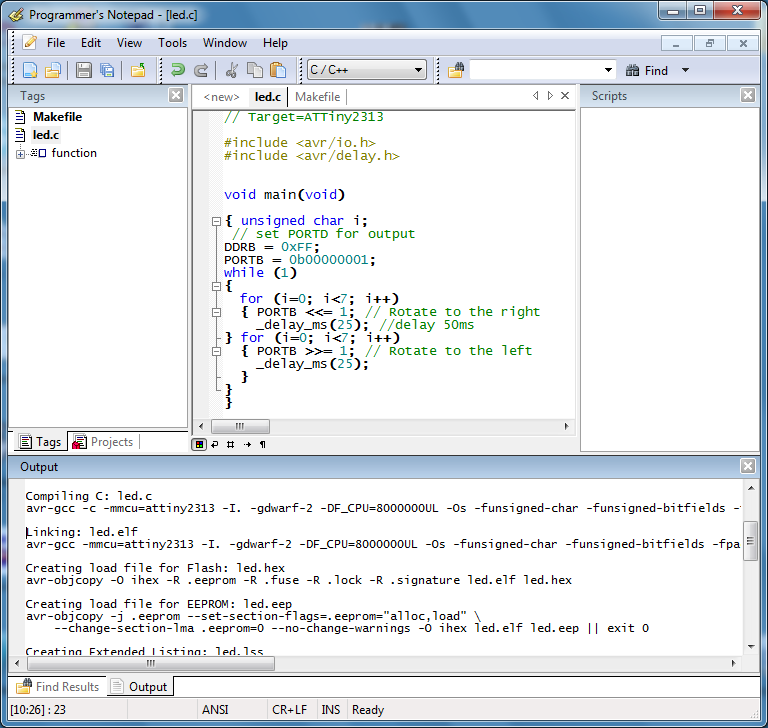
The first two compiled value assignment statements:
void main(void)

{ unsigned char i;
 // set PORTD for output
DDRB = 0xFF;
  34:    8f ef           ldi    r24, 0xFF    ; 255
  36:    87 bb           out    0x17, r24    ; 23
PORTB = 0b00000001;
  38:    81 e0           ldi    r24, 0x01    ; 1
  3a:    88 bb           out    0x18, r24    ; 24
The EEPROM content (led.eep) is now ready, and this can now be burnt into the ATTiny2313 with the avrdude programming utility and with an stk600 (200$) or with an AVRISP (40$) hardware.
Atmel also made its own IDE to which they provide many program libraries - this is called AVR Studio. It contains an integrated C compiler, but the actual Internet using society use the GCC compiler, so the AVR Studio can be configured in a way that it would work with the GCC compiler that can be found in WinAVR.
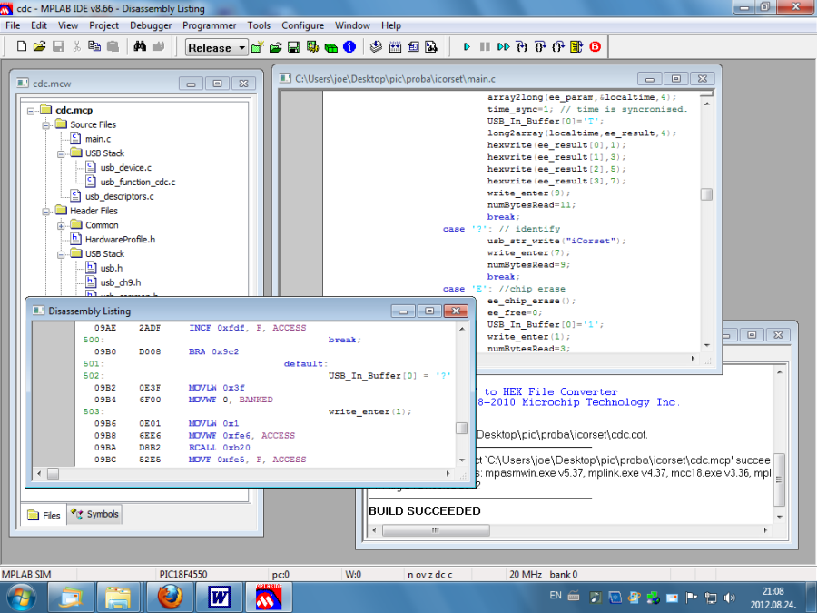
VI.2.2. Microchip: MPLAB IDE and MPLAB-X
At Microchip, there is no GCC support (although the picgcc project exists but it does not have a downloadable version), so the MPLAB IDE can be downloaded free from the website of the company. This contains an assembler compiler (MPASM) for all their products (16xx, 18xx, 24xx, dsPIC), with the exception of the Pic32 family (MIPS core:asm32), and it contains a C compiler with an education licence for the 18 (c18), 24 (c24) and 32 (c32) series. Besides editing, the the IDE supports all the available programmers and debuggers. If the IDE is intended to be used in a comfortable way, we should not accept "full installation", only the already existing (planned) devices and compilers should be installed. MPLAB SIM could be a useful tool with which programs can be executed and debugged without a concrete hardware, on a virtual CPU. The great advantage of a virtual CPU is that it cannot be ruined with a power supply of reversed polarity, contrary to real ones. The Figure VI.4 shows the development of a program code that communicates with the (SerialPort) program that can be found in Section IV.2.23.
The code portion on Figure VI.4 can be burnt into a PIC18f4550 with a PicKit2 (original: 40$, clone: 25$) and after that communication with the hardware is possible through USB.
The problems arising during the development of MPLAB IDE (dependency on Windows) are attempted to be solved in the new MPLAB-X. The NetBeans-based environment runs on both Linux and MacOS-X. This contains the automatic code completion functionality of the Visual Studio and the function definition finder.
VI.3. Programming of distributed systems
With the expansion of Internet and its base protocol, not only interpersonal communication accelerated a lot. Nowadays, supercomputers contain more than one processor with a big clock rate as well as big memories and data storage devices. The clock rate have reached the technological limit, an increase in performance can only be achieved by increasing the number of the basic computing components that can function parallelly in the same time. This can be achieved by encasing more processor cores within the same integrated circuit (Dual, Quad, etc. core).So it was a useful idea to share tasks on the Internet as well. The Internet connection between two machines takes place as a sequential file with the usage of socket software packages. The first method that is based on sockets but making possible an access on a higher level than sockets is remote procedure call (RPC), like that used in SUN NFS Unix-based file servers. However, programmers do not intend to develop protocols, error handling and file access. There are also object-oriented technologies as well that are based on sockets. In the case of these technologies, the properties of objects on a server are accessible on its clients; their methods can be run on servers as simple function calls on clients. Similarly, an event arising on a server can be handled with a triggered method on a client. It is also possible that only one proxy should be assigned to an IP-address and that it is the former that transfers a query of a user to a server computer that is free at that moment. Nowadays, systems with big computing needs work on a similar principle both in commerce and in education. This is the case for example for amazon.com, system of Google or JUQUEEN and JUROPA machines (IBM).
VI.3.1. CORBA
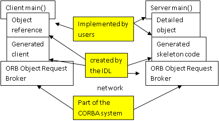
CORBA is a standardized object environment defined by OMG (Object Management Group). Its first version appeared in 1990 with which applications written in different languages and/or running on separate computers can work together. This application can use methods on the remote machines in the same way as on the local machines. An important element of the standard is interface definition language (IDL), which is independent of the actually used compiler (that may compile from C, C++, Java, Cobol and from some other languages). CORBA compilers make function headers (skeletons) for the objects written in IDL for the given language. These skeletons have to be implemented for the given language by programmers: this process is called "mapping". The objects made during this process are called "adapters". Mapping is easy in Java because of the strong object-oriented properties of that language. In C++, a little bit more work has to be carried out to achieve the same: complex data structures have to be used and these may sometimes become mixed with the types of Standard Template Library (STL). The CORBA implementation contains an IDL compiler that compiles to the used language (e.g. C++). An executable program can be created with an ordinary compiler and linker, of course by defining functions compiled from IDL (by "dressing" the skeletons) in the given language. Besides that, it contains native communication components which carry out communication on the Internet on the socket level in a way that is transparent to users. The Figure VI.5 demonstrates the access of an object operating on a server from a client.
VI.3.2. Open-source implementations of CORBA
CORBA is a standard so it cannot be obtained from a manufacturer: many people have implemented that structure. Among these, there are licensed (that can be bought) and open-source versions. The licensed ones are mainly widespread in the financial sector, open-source versions available for free are used for educational purposes.
MICO: www.mico.org contains only Unix API calls, written in C++, developed by the University of Frankfurt. Source files are stored on SourceForge, from where they can be downloaded
JacORB: www.jacorb.org, ORB written in Java, with an LGPL license. Needs JDK 1.6 to function.
TAO: www.ociweb.com, developed by the University of Washington, it has a free and a commercial version. Can be used both under Unix and Windows and there is also a version that runs under a real-time operating system.
ORBiT: orbit-resource.sourceforge.net can be used in basic C and Perl, an open-source CORBA 2.4 implementation. Since it was developed for GNOME system, most Linux distributions contain it. It has a version running under Win32.
The following example carries out a "remote" calculation: the client determines the operation, the server carries it out and then the client prints out the result. When tested, both the server-side and the client-side program run on the same computer. The IDL file is as simple as possible, it contains an interface with two functions:
// Calculator interface: calculator.idl
//
interface Calculator
{
      double add(in double number1, in double number2);
      double sub(in double number1, in double number2);
};
Let's compile it with the idl compiler: /usr/pkg/bin/orbit-idl-2 calculator.idl
orbit-idl-2 2.14.17 compiling mode, hide preprocessor errors, passes: stubs skels common headers
Processing file calculator.idl
Now the skeleton (calculator-skel.c), the stub that can be executed on the client (calculator-stubs.c) and the headers (calculator.h) are generated. The header file contains a CORBA-compatible class (basic C with struct functions):
typedef struct {
  void *_private;
CORBA_double (*add)(PortableServer_Servant _servant, const CORBA_double number1, const CORBA_double number2, CORBA_Environment *ev);
CORBA_double (*sub)(PortableServer_Servant _servant, const CORBA_double number1, const CORBA_double number2, CORBA_Environment *ev);
} POA_Calculator__epv;
These have to be implemented (skelimpl.c):
static CORBA_double
impl_Calculator_add(impl_POA_Calculator * servant,
            const CORBA_double number1,
            const CORBA_double number2, CORBA_Environment * ev)
{
   CORBA_double retval;

   /* ------   insert method code here   ------ */
   g_print ("%f + %f\n", number1, number2);
   retval = number1 + number2;
   /* ------ ---------- end ------------ ------ */

   return retval;
}

static CORBA_double
impl_Calculator_sub(impl_POA_Calculator * servant,
            const CORBA_double number1,
            const CORBA_double number2, CORBA_Environment * ev)
{
   CORBA_double retval;

   /* ------   insert method code here   ------ */
   g_print ("%f - %f\n", number1, number2);
   retval = number1 - number2;
   /* ------ ---------- end ------------ ------ */

   return retval;
}
Now the server-side main program can be the next:
static CORBA_Object
server_activate_service (CORBA_ORB           orb,
             PortableServer_POA  poa,
             CORBA_Environment  *ev)
{
    Calculator  ref = CORBA_OBJECT_NIL;

    ref = impl_Calculator__create (poa, ev);
    if (etk_raised_exception(ev))
        return CORBA_OBJECT_NIL;

    return ref;
}
The service is started in the main() function of the server:
servant = server_activate_service (global_orb, root_poa, ev);
server_run (global_orb, ev);
The stub does not have to be modified on the client, it is only the main() function that has to be written:
static
void
client_run (Calculator service,
    CORBA_Environment *ev)
{
    CORBA_double result=0.0;
result = Calculator_add(service, 1.0, 2.0, ev);
g_print("Result: 1.0 + 2.0 = %2.0f\n", result);
}
This is called from the main() function of the client and the server does the calculation:
./calculator-server the server is launched in the background, and it waits for the connection of the client
./calculator-client the client is started
1.000000 + 2.000000
Result: 1.0 + 2.0 = 3
VI.3.3. ICE – internet communication engine
Having examined the CORBA system, we have found that it can be applied to many tasks; however, most of the programming work has to be used for useless overcomplicated objects and classes. For that purpose, some CORBA developers created a little developer team to create a system supporting access of remote objects in a simplified (but in the same time) extended way by rethinking the principles of CORBA. For that purpose, they founded a company under the name ZeroC (www.zeroc.com). They named their system ICE, and it is available under two licences: GPL and commercial licence. The commercial version (for which we have to pay) comes with a product support. Another advantage of ICE is that it has a version running on touch-screen platforms that are popular nowadays, e.g. IceTouch, which was made for the compiler of OS-X (Xcode) and contains an iOS simulator, too.
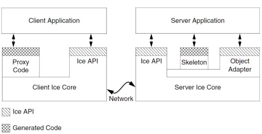
The ICE distribution contains everything the environment needs: devices, APIs, libraries for the creation of object-oriented client-server applications. It supports the compatibility between architectures and languages: a client and a server can run under a different platform and the two may be written in other languages. The descriptor language in which an ICE object is defined is called Slice (Specification Language for Ice). It contains interfaces, operations and data types defined commonly on both the server and a client. These Slice files are compiled by a compiler to API calls, to code portions in different languages, which can be compiled on the currently used system and programming language, but of course only after skeletons are filled in (i.e. the portion between {} of functions are written). Compilation to a given language is called "language mapping". The language used in the Ice system can be C++, Java, C#, Python and Objective-C. The client-side can use PHP as well. The structure of programs using ICE can be seen in the Figure VI.6.
ICE uses its own protocol over IP: this may be TCP or UDP. If objects contain important data, SSL can also be used between servers and clients. Besides ordinary remote objects, it offers extra services, like IceGrid, in which more servers can contain the same object for the purpose of load-balancing; or IceStorm, which share events between publishers and subscribers interested in those events.
In the following simplified example, the ICE server-side of an industrial robot is created. The clients connected to the robot are able to move the robot and to obtain the actual coordinates. The slice definition file is the following (KukaRobot.ice – it can only be opened as a text file in the Visual Studio):
module CyberLab
{

  struct e6pos
  {
    float x; // x,y,z are millimeters
    float y;
    float z;
    float a; // a,b,c angles in degrees
    float b;
    float c;
  };


  interface Robot6Dof
  {
    void GotoHome(); // home position defined in robot program
    e6pos GetPosition(); // where are you ?
    void GotoPosition(e6pos p); // go to the position
  };
};
When this file is compiled with slice2cpp.exe, 2 files are created: KukaRobot.cpp and KukaRobot.h. This is the so-called skeleton, in which the defined methods figure as abstract virtual member functions:
virtual void GotoPosition(const ::CyberLab::e6pos&, const ::Ice::Current& = ::Ice::Current()) = 0;
The last function of the interface can easily be recognized. In order to instantiate the class, we have to define this function. A new class (the implementation class: Robot6DofI) is derived from the class named Robot6Dof. This new class contains the implementation of these member functions – prototypes:
class Robot6DofI : public Robot6Dof {
public:
    virtual void GotoHome(const Current& c);
    virtual e6pos GetPosition(const Current& c);
virtual void GotoPosition(const e6pos& e6, const Current& c);
};
and defintions:
void Robot6DofI::GotoHome(const Current& c)
{
    Send_command_to_robot(CMD_ROBOT_HOME);
}

e6pos Robot6DofI::GetPosition(const Current& c)
{
    e6pos poz;
    Send_command_to_robot(CMD_ROBOT_GET_POSITION,poz);
    return poz;
}

void Robot6DofI::GotoPosition(const e6pos& e6, const Current& c)
 {
     Send_command_to_robot(CMD_ROBOT_GOTO_POSITION,e6);
 }
When these functions were defined, we used the already existing communication functions that sent instructions through RS-232 with the robot. The last thing to be done is writing the main program and creating the communication adapter (on the basis of the ICE demo):
int _tmain(int argc, _TCHAR* argv[])
{
    int status = 0;
    std::string s1="KukaRobotAdapter";
    std::string s2="default -p 10000";
    Ice::CommunicatorPtr ic;
    Ice::InitializationData id;
    argc=0;
    try
    {
    ic = Ice::initialize(id);
    Ice::ObjectAdapterPtr adapter=ic->createObjectAdapterWithEndpoints
(s1,s2);
    Ice::ObjectPtr object = new Robot6DofI;
    adapter->add(object,ic->stringToIdentity("KukaRobot"));
    adapter->activate();
    ic->waitForShutdown();
    }
    catch (const Ice::Exception& e)
    {
        cerr << e << endl;
        status = 1;
    }
    catch (const char* msg)
    {
        cerr << msg << endl;
        status = 1;
    }
    if (ic)
    {
        try
        {
            ic->destroy();
        }
        catch (const Ice::Exception& e)
        {
            cerr << e << endl;
            status = 1;
        }
    }
    return status;
}
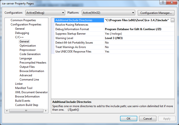
Do not forget about setting the ICE include and library directories in the Settings of the project because it is not able to compile and link the program without them.
When compilation has taken place correctly, the thing left to be done is making available the DLLs belonging to the ICE while the program runs and then starting the server. When the file named KukaRobot.ice is sent to the foreign partner, the latter creates the client (in a language, e.g. C#) and can control the robot remotely.