Chapter 2. Classification of electric motors
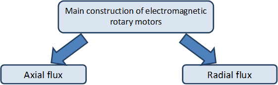
In the chapter title the term electric motors was intentionally used instead of the commonly used electrical machines, because we would like to express that neither the transformers nor the generators used in power plants - both are parts of the topic electrical machines - will be discussed in this syllabus. Naturally the majority of the motors discussed here have got energy regeneration mode (acting as generators) which also can be used for braking and furthermore they can be used for energy recuperation to achieve better efficiency. Some of the motors like the ultrasonic motors however cannot be used for energy recovery. Several different methods existing for classify the electric motors. From the users’ point of view the main difference between electric motors is the movement type (i.e. linear or rotary). See Figure 2-1.
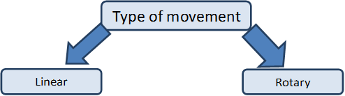
In theory all types of electric motors can produce linear and rotary movement it is only a question of construction of the motor. Most of the electric motors producing rotary movement thus in this syllabus only the rotary motors will be discussed.
The main question about the working principle of the different type of electric motors is which medium is used to relay the rotary movement from the motor’s stator to the rotor. (See Figure 2-2.)
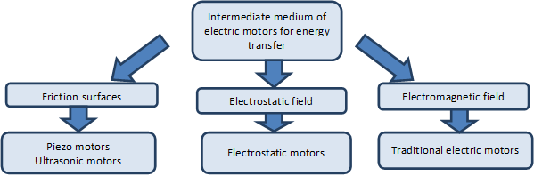
Negotiations about this question have only begun in the late 20th century. In the 20th century only the electromagnetic motors were considered as electric motors. Although the working principles of the electrostatic motors were known in the middle of the 18th century but electrostatic motors couldn’t produce significant amount of torque at that time and technological level, thus they were used to drive instruments rather than for energy conversion. Their importance has increased again in Micro Electro Mechanical Systems (MEMS), where as a general rule to be stated the inductors were replaced by capacitors. The electrostatic motor is a type of electric motor that operates on the basis of attraction and repulsion of the electric charge, thereby the coil is replaced by condenser. An important difference between the two motor types is that in case of the electromagnetic motors, the motor power varies approximately linearly with the volume, while the output power per unit volume may increase significantly when reducing the size of an electrostatic motor. The reason is that the maximum available magnetic flux density in the air gap inside the motor depends on the saturation of the ferromagnetic material used in the motor. In the electrostatic motors the maximum field strength is limited by the dielectric strength of air, whoever it is known, that the dielectric strength of the air at same values of the air’s physical properties (temperature, pressure, humidity) is increased for small electrode distances according to the Paschen’s law. Therefore, the integration of many small electrostatic motors can open up interesting perspectives. In robotics often mentioned problem is that if we compare the ratio of human muscle and total body weight ratio to the motors performing the motion of robots and robots’ full weight, then we can see that the drive mechanism is relatively too heavy for robots. One solution could be to replace the current motors ferromagnetic material. The so-called coreless motors were appeared as one trend of weight reduction, but in this context the so-called high-performance electrostatic motors are providing an alternative. At the time of writing this note the electrostatic motors are still in the experimental stage, despite this as an encouraging result a 100W electrostatic motor was appeared on the market, which weighs approx. an order of magnitude smaller than an electromagnetic motor weighs with similar nominal power.
The Piezo motors, also known as ultrasonic motors are forming the youngest generation of electric motors. Nowadays the Piezo motors almost became the dominant electric motors of the camera optics drive systems. Their advantage is the faster and more silent positioning on focus. A small disturbance can be caused by trademark reasons; the various manufacturers had to use different names.
Some trademarks and their manufacturers:
-
USM (UltraSonic Motor) (Canon);
-
SWM (Silent Wave Motor) (Nikon);
-
HSM (HyperSonic Motor) (Sigma);
-
SSM, (SuperSonic Motor) (Sony);
-
SDM (Supersonic Drive Motor) (Pentax);
-
SWD (Supersonic Wave Drive) (Olympus);
-
XSM, (Extra Silent Motor), (Panasonic);
-
USD (Ultrasonic Silent Drive) (Tamron).
In addition to the Photography industry the term most commonly used is USM. In the micro-and nanotechnology the Piezo actuators also have a particular role. Piezo motors should be used in places where no ferromagnetic materials can be used for some reasons for example in MRI devices a magnetic field with a magnitude of 9T may possible, in ferromagnetic materials a magnetic field with a magnitude of 2 T can also cause problems. But the use of electromagnetic motors is also not advisable in the vicinity of superconductors. Later on we briefly describe the electrostatic and the Piezo motors.
2.1. Electromagnetic motors
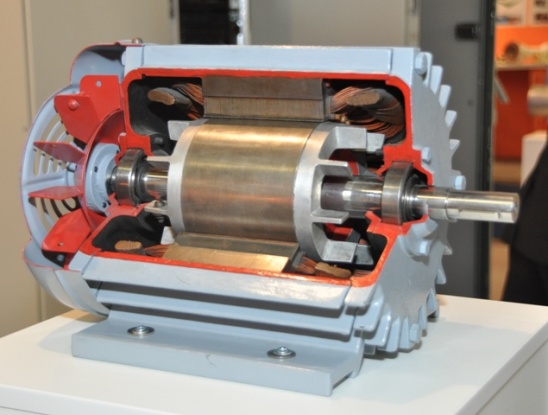
The rotary motors are consisting of a tubular section and a cylindrical section. The rotational movement is enabled with the use bearings. Generally, the tubular part is the stator fixed to the external environment, in which the cylindrical portion rotates, but the roles can mixed up, typically in the case of wheel hub motors and fans and including the so-called Coreless motors. (See Figure 2-3.)
The laws of electromagnetic machines:
-
The operation of electromagnetic machines is based on the interaction of two electric or magnetic fields which are at rest relative to each other.
-
The operation of electromagnetic machines is reversible i.e. the direction of the energy flow can be reversed.
-
Theoretically the efficiency of the electromagnetic machines can approximate the 100 % freely.
The most important step of operation of the electromagnetic motors is the creation of the magnetic field (excitation). The excitation can be inserted on the:
-
stator (one side excitation);
-
rotor (one side excitation);
-
both (two sides excitation).
The excitation can be accomplished by
-
winding;
-
permanent magnets.
The excitation must be varied relative to the stator or to the rotor. This can be achieved only if an external power source is used for the excitation of the windings. Thus always at least one of the stator-rotor excitations is achieved with windings, the other one can be a winding or a permanent magnet. This means that on every electromagnetic motor there is an actual winding, but in general sense all of these motors can be modelled with a stator winding and a rotor winding, which are in inductive interaction with each other.
The magnetic field lines are always forming a closed curve. In terms of the magnetic field fundamentally two different types of the electromagnetic motors can be distinguished. See Figure 2-4.)
In the case of an exciter winding with a number of turns N the following can be written:
|
|
(2.1) |
Where is the exciting current, is the magnetic field strength, and is the closed curve of the magnetic flux’s path.
It is known that to describe the magnetic field two different physical quantities are used. One of them is the magnetic induction that describes the total magnetic field. The other one is the magnetic field strength, which takes into account only the impact of the so-called external currents. The relationship between the two quantities:
|
|
( 2.2 ) |
Where is the permeability of vacuum, and is the relative permeability. The foregoing provides a link between the two different approaches of magnetic field, the latter taking into account the effect of the material. Unpaired electrons (on a given the electron path, only one electron orbits, details should be found in the scope of quantum physics) in materials have a permanent magnetic moment, which can strengthen the effect of sending magnetic field. This can be modelled simply with an elementary loop current consequence of the electron’s orbital movement. This can be construed as the elementary loop currents formed inside the material are creating elementary magnetic fields as well. The neighbouring elementary magnetic fields can strengthen each other while they are trying to organize themselves in a parallel shape (well below of the Curie temperature). The reasons for this phenomenon are also lying in the scope of quantum physics. So-called domains are formed inside the material, in which the elementary magnetic moments are completely parallel, however the absence of an external magnetic field the magnetic orientation of each of the domains are random, thus the individual domains are impairing each other’s effect (the magnetic field lines can close inside the material) and only a small magnetic field can be measured from the outside.
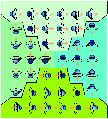
External magnetic field causes at first a shift of the boundaries of the domains so that it will strengthen the external magnetic field. The shift of boundaries has a nearly linear range where the total magnetic field varies nearly proportionally whit the external magnetic field, in which the domains are then rotated into the direction of the external magnetic field. When all of the domains were turned, than the material can no longer continue to strengthen the external magnetic field, this is called full saturation. In terms of torque generation the magnetic induction is dominant. The goal is to achieve the maximum possible magnetic induction and minimize the required excitation. This is the reason that the electromagnetic motors are made of ferromagnetic material. In case of ferromagnetic materials at unsaturated state. This means that the same magnetic induction can be created and the scattered flux also can significantly be reduced if ferromagnetic material is used in the magnetic circuit and if the machine is designed so that the saturation cannot occur, than the excitation current can be reduced up to several orders of magnitude. Of course, there is an air gap between stator and rotor because of constructive reasons, but in terms of the magnetic circuit the goal is to the air gap should be as small as technologically possible. As we will later see, the spatial distribution of the air-gap flux density can be also an important design consideration, and therefore there are motors, where the size of the air gap is not constant, but for those motors is also true that the minimal air gap should be as small as possible.
2.1.1. Torque of electromagnetic motors
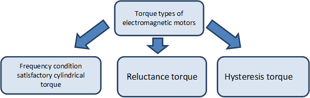
The unified theory of electrical machines distinguishes three kinds of steady-state (non-zero mid value) torque types. (See Figure 2-6.)
The first two torque types (similarly as the electromagnets’ pull force) can be calculated via the use of the so called principle of virtual work. According to this principle for the motor’s infinitely small rotation at constant excitation will change the energy stored in the motor’s magnetic field. It is assumed that the magnetic field neither uses electric power from the electric circuitry nor gives unnecessary energy to it. According to the principle of energy conservation the change in the energy amount of the magnetic field equals to the change of the mechanical energy needed for the same rotation assuming rotor angular speed is constant.
|
|
( 2.3 ) |
In case of windings the energy of the magnetic field can be easily calculated as energy stored in an inductor. If the number of turns on the winding is noted as the energy stored in an inductor:
|
|
( 2.4 ) |
Where if than is the self-induction factor, if than the mutual inductance.
Because of symmetry reasons:
|
|
(2.5) |
If the time is stopped at a particular moment, the current will have to be seen constant, and therefore the induced voltage is zero on the winding, i.e. the magnetic field really does not take up and does not give off energy from and to the electric circuit. The change in the energy of the magnetic field is derived solely from changes of the inductance. The inductance changes due to changes in the position of the rotor. Indicate the values of the frozen currents with and the torque in the particular moment:
|
|
(2.6) |
Of course, if the time freezes at every moment one after another then the following can be written:
|
|
(2.7) |
2.1.1.1. Cylindrical torque of Single-phase motor
The frequency condition is applies for motors with inductive connection, cylindrical interior design (with constant air gap) and the motors are modelled on both sides with coils, thus the corresponding torque is called cylindrical torque.
Assumptions:
-
single-phase windings can be found on both sides;
-
eddy currents aren’t formed on either side and the magnetizing curve of the iron core has no hysteresis;
-
the spatial distribution of the induction in the air gap generated by each coil is sinusoidal;
-
the principle of superposition is valid for the magnetic field (magnetization of ferromagnetic material is linear and non-saturated);
-
the function of each coil’s current is a sine wave (as a limiting case including the direct current and permanent magnetic excitation as well);
-
the supply currents on both sides are in the same phase;
-
the coils are symmetrical (the mutual inductance is a sinusoidal function of the rotor’s angular position with a period equal to the time needed for one rotation).
It is known, that
|
|
(2.8) |
Where and are the self-induction factors in the stator and the rotor, is the mutual inductance in linear case, and are the exciter currents in the stator and rotor respectively and is the rotor’s actual angular position. In (2.8) only the third part is a function of the rotor’s actual angular position and in case of constant angular velocity can be calculated as:
|
|
(2.9) |
Where is the load angle (the starting angular position of the rotor, depending on the load). Based on (2.3) and (2.8) substituting the sinusoidal currant and (2.9) we can get
|
|
(2.10) |
Where is the amplitude of the stator’s current, is the amplitude of the rotor’s current, is the maximum value of the mutual inductance between the stator and the rotor (in the angular position of ), is the angular speed of the rotating magnetic field of the stator relative to the stator, is the angular speed of the rotating magnetic field of the rotor relative to the rotor, is the rotor’s angular speed relative to the stator. In general case (2.10) would produce a pulsating torque (with zero mid value). This fact has a strong relationship with another fact, that a single-phase coil can only produce a pulsating magnetic field. The frequency condition refers for those cases where (2.10) have a non-zero mid value. The first condition is the sinus value of the load angle shouldn’t be equal to zero.
|
|
(2.11) |
Further conditions, which can’t be satisfied simultaneously (therefore a pulsating torque is always present in case of a single-phase motor)
2.1.1.2. Cylindrical torque of Multi-phase motors
In case of multi-phase motor windings of the stator and the rotor are modelled with two coils on both sides.
Assumptions:
-
eddy currents aren’t formed on either side and the magnetizing curve of the iron core has no hysteresis;
-
the two windings are perpendicular on each other on both sides;
-
the two pairs of the windings are geometrically completely symmetrical, (the values of the mutual inductances are changing in sinusoidal relationship with the rotor’s angular position, and the with has period equal to the time needed for one rotation);
-
the spatial distribution of the induction in the air gap generated by each coil is sinusoidal;
-
the principle of superposition is valid for the magnetic field (magnetization of ferromagnetic material is linear and non-saturated);
-
the function of each coil’s current is a sine wave (as a limiting case including the direct current and permanent magnetic excitation as well);
-
the currents supplying the motor are symmetrical on both sides, the amplitude of the feeding currents’ of the windings are equal on the same side;
-
The phase of the supplying currents is 90º (one of the supplying currents is sinusoidal the other one is cosinusoidal);
-
Starting phases of all of the currents are zero (purely sinusoidal or cosinusoidal).
In the two-phase winding system only the rotor’s angular position dependent component of the stored energy is given, because all other parts are eliminated while making the partial derivatives.
|
|
(2.16) |
|
|
(2.17) |
Based on the assumptions for the feeding current and (2.9)
|
|
(2.18) |
Utilizing the sinusoidal functions and the symmetry of the windings the equation of the torque can be simplified as were before using (2.18). This has a strong correlation with that the two-phase winding supplied by symmetric, but phase shifted current can generate rotating magnetic field.
|
|
(2.19) |
The frequency condition is one of the single-phase cases.
|
|
(2.20) |
If the (2.20) frequency condition is true than the torque is constant (no pulsating torque):
|
|
(2.21) |
(2.20) is one frequency condition satisfying case.
DC current supplied DC motor
|
Constraint condition |
Resulting condition |
||
|
|
|
(2.22) |
The above means that because of the commutator the current of the rotor which seems from the exterior standing is actually rotating in the opposite direction of the rotor with the exact same angular speed compared to the rotor.
AC current supplied DC motor (let be the angular frequency of the AC current)
|
Constraint condition |
Resulting condition |
||
|
|
|
(2.23) |
It can be seen that there is no theoretical obstacle for supplying a DC motor with AC current. This is the theoretical basis of the universal motors.
DC current supplied / permanent magnet rotor excited motor
|
Constraint condition |
Resulting condition |
||
|
|
|
(2.24) |
In these machines steady-state torque is only generated when the angular frequency of the AC current supplying the rotor, more specifically the angular speed of the magnetic field generated by the stator’s winding is equal to the angular speed of the rotor, this angular speed is called synchronous speed. Between the axis of the rotating magnetic field and the axis of the rotor is the load angle. Thus follows if the synchronous machine is supplied directly from sinusoidal voltage network than synchronous machine has no starting torque. In contrast, if the synchronous speed is controlled by electronics than any speeds can be reached within the operating range. The condition for this is to know the angular position of the rotor (actual angular speed). This is the theoretical basis of the brushless motors.
Asynchronous (induction) motors
|
Constraint condition |
Resulting condition |
||
|
ha |
(always satisfied) |
(2.25) |
There is no supply on the rotor of an asynchronous motor (an exception is the doubly fed asynchronous motor), thus by default the angular frequency of the induced voltage on the rotor is equal to the difference between the synchronous speed and the angular speed of the rotor (as a boundary situation at the synchronous speed the amplitude of the induced voltage is zero). In the above cases motors with DC current excitation on one side or AC current with identical frequency and phase excitation on both sides were explained (AC current supplied DC motor), therefore the last condition was irrelevant. In case of induction motor the last condition would only be satisfied if the winding on the rotor would be purely ohmic but in a real motor this never happens. It is clear without detailed explanation that in case of purely inductive winding on the rotor (with the rotation of currents in the winding of the rotor by 90º and subtracted back to (2.18)) the generated torque would have a zero middle value. If someone would like to produce the windings on the rotor from superconductors than the asynchronous motor wouldn’t have any torque output. In other words in case of asynchronous motor the simplified form of torque equation (2.19) should have a part, which takes in to account the impedance of the winding of the rotor with a cosine function of the phase angle, which has a maximum value at the zero phase
angle point (in case of pure ohmic impedance). The angular frequency – torque curve of the asynchronous motor can also be interpreted. At the synchronous speed the motor don’t generate any torque because the current of the rotor is zero. As the slip is increased so do increasing the induced voltage of the rotor, and thus the amplitude of the current is increasing as well. The ohmic resistance of the rotor winding independent from the slip (neglecting the skin effect), in contrast, the inductive reactance of the winding will increase as the slip is increasing, thus worsening the phase angle of the rotor current in terms of the maximum available torque. There are two opposite effects what are prevailing if the slip is increased, one of them is increasing the other one is decreasing the generated torque. In these cases there is always an optimal operating state, where the torque is at maximum, this is called pull-out torque. The deep groove and double squirrel cage motors are designed intentionally so that the skin effect may improve the phase of the rotor current at the start of the motor. Thus higher generated torque can be reached with less current consumption (details are known from the basics of asynchronous motors).
Remarks
-
There are no limits for the values of the currents in (2.20), but the linear magnetic behaviour condition of the materials should be provided, if the excitation is too large the magnetic material can reach saturation.
-
In most of the practical applications the supply is a voltage source, thus opposing the approach of the above calculations, the actual torque can’t be calculated from the known current but instead the actual load torque will determine the actual current consumed.
2.1.1.3. Reluctance torque
If the air gap height is not constant (typically when protruding poles can be found on the rotor), than on the other side (typically on the stator) the self-induction factor will became a function of the angular position of the rotor. Usually the reluctance and cylindrical torques are occurring combined, here the only case will be described where the stator is supplied and the rotor has protruding poles without excitation. Thus this means there are no eddy currents on the rotor, if eddy currents would develop on the rotor, than they should be considered as excitation and that will lead to a similar operating mode as the induction motors have. In case of soft iron core rotor the polarity is irrelevant, therefore the inductivity value is changing a period of two during one rotation of the rotor.
Assumptions:
-
one single-phase winding can be found on the stator;
-
eddy currents aren’t formed on either side and the magnetizing curve of the iron core has no hysteresis;
-
the principle of superposition is valid for the magnetic field (magnetization of ferromagnetic material is linear and non-saturated);
-
the protruding poles and the stator winding is symmetrical (the self-inductance is a sinusoidal function of the rotor’s angular position with a period double the time needed for one rotation);
-
the function of the coil’s current is a sine wave.
Single-phase case will be detailed here, momentary value of the energy stored in the stator winding:
|
|
(2.26) |
where is the angular position independent part and is the angular position dependent part of the stator self-induction coefficient. In (2.26) only the last part is angular position dependent, and assuming constant angular speed it can be described by (2.9). Based on (2.3) and on (2.26) and substituting the sinusoidal currents and (2.9)
|
|
(2.27) |
Using trigonometric identities
|
|
(2.28) |
Constant torque can be achieved based on the first part of (2.28) if
|
|
(2.29) |
This means that the reluctance motor has starting and holding torque. Based in the second and third part of (2.28)
|
|
(2.30) |
this means for reluctance motors the frequency condition can be satisfied only at the synchronous speed, but there is no preferred direction of rotation (the motor can be rotated in both directions at the same power supply). The load angle is multiplied by 2, which means the maximum torque is generated if. All of the above statements are in full accordance with our physical ideas of the reluctance motors.
Remarks
-
The single-phase reluctance motors always have pulsating torque component similarly to the single-phase cylindrical torque, but in multi-phase reluctance motors the pulsating torque component can be eliminated similarly to the multi -phase cylindrical torque.
-
There is a preferred rotational direction for multi-phase reluctance motors.
-
In general the AC motors are supplied with sinusoidal voltage and therefore within the meaning of Faraday's law of induction the flux is sinusoidal, but in this case because of the variable self-induction factor the current in the coil cannot be sinusoidal.
-
In case of real reluctance motors some extent of cylindrical torque is generated because of the eddy current developing on the rotor, but in some cases the rotor is intentionally excited, thus the cylindrical and reluctance torque should be summed.
2.1.1.4. Hysteresis torque
Hysteresis torque is mainly utilized in small and fractional-horsepower machines. These synchronous motors are excited with permanent magnet rotor in accordance to the (2.24) frequency condition, where in asynchronous mode the rotor is allowed to change its magnetization. The eddy currents of the motor are still neglected but due to the magnetic reversal of the rotor the hysteresis loss must be taken in to account and therefore (2.3) cannot be used directly.
Suppose that we create a rotating magnetic field with a multi-phase winding and the motor is stalled. Let denote the energy needed for the magnetic reversal. Let denote the mechanical energy needed for the magnetic field rotated once. Based on conservation of energy
|
|
(2.31) |
Assuming constant torque
|
|
(2.32) |
If the motor is allowed to rotate than the rotation angle needed for one hysteresis loop in not equal to and the kinetic energy of the motor must be taken in to account also in the energy balance.
|
|
(2.33) |
Continuing the calculations with power instead of energy and neglecting stator side losses the mains absorbed power is equal to air-gap power.
|
|
(2.34) |
Equation (2.34) even has the same form as the air-gap power equation of the asynchronous motors with a difference that the power of copper loss is replaced by the power of the hysteresis loss. Also here the mechanical power and the power of the hysteresis loss can be expressed with slip and air-gap power:
The power of the hysteresis loss is independent from the load unlike the power of copper loss, and is only dependent of the relative angular velocity between the rotor and stator i.e. dependent on the slip. Consequently the air-gap power is constant, but furthermore the torque of the hysteresis motor is constant in the asynchronous mode.
|
|
(2.37) |
Based on (2.37) the pure hysteresis motor will spin up in asynchronous mode generating constant torque until it reaches the synchronous speed then staying at synchronous speed it will continue rotating as a synchronous motor with a load angle depending on the magnitude of the load. In reality eddy currents are also developing on the rotor which are also generating cylindrical torque that satisfies the (2.25) frequency condition.
2.1.1.5. The impact of electronic power supply to the torque
In the previous chapters the spatial and temporal sinusoid being of functions was an important condition. The former one can be ensure by a proper mechanical construction and the power supply does not have any impact, but the later one is depending only on the power supply. In case of electronically powered motors harmonics in the excitation and pulsating torque caused by them, furthermore heightened losses compared to pure sinusoid supply must be expected. In extreme cases an electronically powered asynchronous motor can be overloaded (overheated) even operated at nominal speed and load conditions. This also means that if an induction motor is supplied directly from the electrical network and next to the motor is a power electronics device with non-sinusoidal power supply is operated and therefore the device is distorting the voltage of the electrical network than pulsating torque caused by harmonics in the excitation and heightened losses must be expected as well. Application of different type of filters is advisable if power electronics are operated to prevent the so called EMC (Electromagnetic compatibility) problems. With the use of control electronics the synchronous speed can be gradually changed both to synchronous and asynchronous motors.
2.1.2. Field-oriented approach method
There is force acting on a current-carrying wire when placed in a magnetic field.
|
|
(2.38) |
where the overbar denotes spatial vectors, is the force, is the magnetic induction, is the direction vector of the current-carrying wire and is the magnitude of the torque generating current.
The cross product is maximal when the magnetic induction vector and the path of the current are perpendicular to each other. This can be achieved by mechanical construction when the magnetic field is radial and the winding is axially oriented or inversely.
Based on (2.38) in the air-gap the magnitude of the magnetic field is critical, i.e. the magnetic induction should be maximal where the current-carrying wire is located in space.
Goal:
-
the value of the magnetic induction should be tuned by the excitation to an optimal value from the iron core’s point of view (to the maximum possible value, but way below of the saturation);
-
in case of flux weakening the magnetic induction should be controlled by the excitation;
-
the torque should be controlled only by the torque generating current.
The above principle can be most easily achieved with externally excited DC motor, thus these motors were used in classical servo drives. Nowadays this principle can be achieved even with induction motors.
Steps:
-
voltage, current and speed of the motor are measured (speed is approximated in sensor less applications);
-
based on the measurements the differential equation of the motor is solved for the magnetic flux;
-
currents are transformed in to the synchronously rotating coordinate system, where that orientation of the synchronously rotating coordinate system is searched for where and can be separated easily;
-
a controller is to be designed for and in the synchronously rotating coordinate system;
-
the control signals are transformed back to the stationary coordinate system;
-
the control signals are routed to the stator using PWM (Pulse Width Modulation).
2.1.3. Types of electromagnetic motors
The largest selection is available from the rotary electromagnetic radial flux type motors. All types will be discussed in detail in a later chapter. Here an overview will be given with a summary of the most important motor types. See Figure 2-7.
-
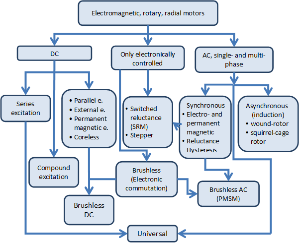 Figure 2.7. Most commonly used motor names
The DC and AC motors are the two most common motor types. The rotor of the former one is powered by DC voltage the stator if the later one is powered by sinusoidal voltage. The sinusoidal voltage can be single-phased but almost everywhere three-phase motors can be found if closed loop control is used. From the classification’s point of view it is an important property that in DC motors the magnetic field in the air-gap is trapezoidal, in AC motors it is sinusoidal.
DC motors can be further classified based on their excitation type. In the case series excited DC motors the rotor and the exciter winding which is developing the magnetic field are coupled in series together, in the case of parallel excitation they are coupled together in parallel. The supply of exciter winding can be independent from the rotor winding (this is called external excitation), or the exciter winding can be replaced by permanent magnet. Particular mention should be made for the coreless motors (these motors are available both in axial and radial flux type). Finally the so called compound or mixed excitation DC motors also exist. These motors have two exciter windings. One of the windings is coupled in series the other one is coupled in parallel. Particular mention should be made for the so called coreless motors, where this expression is valid only for the rotor more accurate name is coreless rotor motors. The rotor is assembled with epoxy based glue, thus no eddy currents are developing on the rotor and this is beneficial for the efficiency. One of their main advantages is the speed, because of the low moment of inertia of the rotor. The mechanical time constant can be in the millisecond order of magnitude, but typically such motors can be found only in the category of 100 W rated power or lower. The mechanical construction can be radial or axial flux type. For the radial type the rotor is cylindrical around the stator.
In case of classic AC motors the most important feature is the sinusoidal spatial distribution of the magnetic field in the air gap, which is sinusoidal in time also, because of the sinusoidal excitation voltage applied on the stator. If only one winding is excited then pulsating magnetic field will develop. The number of phases is also an important feature. If we want the magnetic field to have a rotating component, then two phase windings are needed spatially shifted around the circumference, which are supplied by time-shifted (phase shifted) voltage. Three phase windings are the optimal from many points of view. The non-industrial consumers (i.e. flats, offices) are supplied with single-phase power supply and therefore single-phase AC motors are required (for example older type washing machines, vacuum cleaners, or power tools). The importance of these machines is gradually decreasing, because the majority of motors are electronically supplied (even modern domestic machines) and with the use of power electronics any number of phases can be produced.
In case of three-phase AC motors the spatially- and time-shifted power supply will produce a rotating magnetic field and based on that the rotor will rotate together with the magnetic field or not in the motor mode operation we distinguish between synchronous and asynchronous motors. In case of classic (supplied by three-phase sinusoidal voltage) synchronous motors an asynchronous phase is required to be able to start the motor and reach the synchronous speed. The asynchronous motors are also called as induction motors. The rotor of asynchronous motors may contain actual winding and the terminals of the winding are slip rings. Thus these motors are also called slip ring motors. The rotor winding can be replaced by a short circuited cage thus these motors are called short circuited or squirrel cage motors. The synchronous rotation between the rotating magnetic field and the rotor can be reached if an electro- or permanent magnet is placed on the rotor. Further types of synchronous motors are the hysteresis and reluctance motors. The so called universal motors can be found mainly in power tools, which can be supplied with both AC and DC current. In theory the series excited DC motors can be supplied with AC current also. The difference between universal motors and series excited DC motors is that the rotor of universal motors is plated to minimize the core loss.
In this lecture note the single-phase motors won’t be discussed (in servo drive applications they are not used). For the classification of motors be complete in Figure 2-8. the most important single-phase motors are collected. Rotating magnetic field cannot be produced with single-phase winding only pulsating. In a stationary (not rotating), short-circuited winding will not develop torque if placed in a pulsating magnetic field, in other words the pure single-phase motor does not have starting torque. Conversely if the winding is rotating already in a pulsating magnetic field, then the torque will develop. The starting of the single-phase motor is critical. For this we can use partially shaded-pole, or split-phase, i.e. spatially shifted winding which is supplied through a capacitor and the capacitor will make the phase (time) shifting. The starting capacitor is only active when starting the motor and will be switched of once the motor is rotating. The run capacitor is always active, or we can use starting and run capacitors in combination. The universal motor is also a kind of single-phase motors.
-
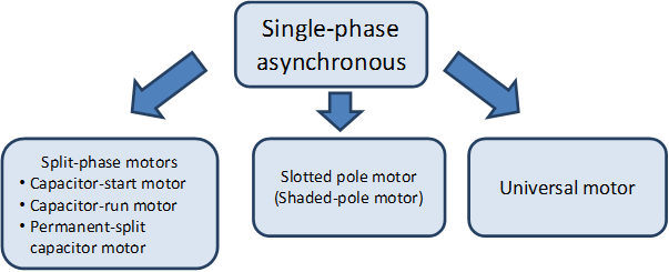 Figure 2.8. Single-phase asynchronous motors
The classical DC and AC motors can be operated without control electronics but if closed loop control is required than use of electronics is essential. There are motors however which cannot be operated without electronics. These motors are considered as synchronous machines (noted with arrows in Figure), but from these motors the classical synchronous motor specific asynchronous mode is missing, instead they can be accelerated or decelerated with the continuous change of the synchronous speed with the use of the electronics adapting to the speed of the rotor. This means also that instead of using asynchronous winding the rotor should be equipped with angular position sensor. Nowadays the so called sensor less drive is fashionable, where the angular position and angular speed of the rotor is approximated using mathematical calculations. The ordinary classification of electronically operated motors (AC and DC) can be confusing, and therefore was kept as a separate type. Including the stepper motors, switched reluctance motors and the brushless motors, which can be classified based on the shape of the magnetic field in the air gap. If the magnetic field in the air gap similarly to the DC motors is trapezoid, then the usual appellation is brushless DC motor (BLDC). If the magnetic field in the air gap similarly to the AC motors sinusoidal, then the usual appellation is brushless AC motor (BLAC). The PMSM is also a commonly used name; it is the abbreviation of the permanent magnet synchronous motor. The name on its own does not give information whether or not these motors are electronically operated, but usually only the electronically operated motors are considered as PMSMs. The brushless motors are also called electronically commutated (EC) motors.
The Figure 2-7. is structured vertically but a number of horizontal correlations can be highlighted. In several motor types it is important for the torque generation that winding less (no excitation) protruding poles can be found on the rotor (the generated torque can be further increased if the poles are excited). These motors are called reluctance (magnetic resistance) motors. The name indicates that the magnetic resistance in the air gap is not constant. ???
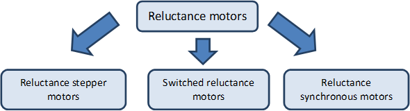
Figure 29. summarizes the different types of reluctance motors. Basically the reluctance motors should be regarded as synchronous motors. The reluctance synchronous motors are supplied with three-phase sinusoidal voltage if operated without electronics, and there are windings on the rotor which are operated asynchronously thus taking care of the spin up of the motor. In case of switched reluctance motors the actual angular position of the rotor determines the excited windings on the stator. It follows that we must measure the actual angular position of the rotor. The switched reluctance motors are the most simplest by construction, there is no winding rotor on the Figure 2-9. .
In case of reluctance stepper motors the rotor will take an orientation according to the excitation of stator winding.
The permanent magnet is a fundamental component in many motor types. See Figure 210.
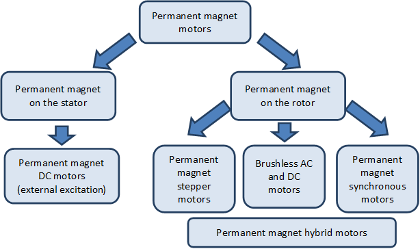
In comparison to the Figure new subclasses are the stepper motors with permanent magnet rotor and the hybrid motors. The hybrid name means the combination of permanent magnetic and non-permanent magnetic materials in the rotor. These motors are used in electric powered cars where the so called flux weakening technique is needed in order to reach higher angular velocities. The flux weakening is analogous to the mechanical torque converters used in motor vehicles, where if the angular speed is increasing so decreases the generated torque. In the low power (10 W) motors permanent magnet is used since long time ago, but for the appearance of the several kW brushless motors the spread of the rare earth magnets was a requirement.
2.2. Electrostatic motors
As the technology supporting our life of future, such as an energy problem and an aging society with fewer children, development of a hybrid car, an electric vehicle, and the robot that supports care and a life of people is furthered. And in order to develop these products, the motor which it is Small and Easy to treat and High efficiency and High power is indispensable.
The electromagnetic motor which has spread most now has a tendency which weight increases and efficiency drops with a higher power. These are the big problems as a future car or a robot's motor.
SHINSEI Corporation has till now offered the ultrasonic motor as an effective motor in the nonmagnetic environment, such as MRI which are medical facilities, superconductivity experiment equipment, etc.
The High Power Electrostatic Motor developed this time is a new style motor constituted by the technology in which ultrasonic motors completely differ. The High Power Electrostatic Motor (following ESM65-TR1) made as a trial production model is very lightweight compared with the electromagnetic motor of the same power. And on ESM65-TR1, since there is almost neither a friction part nor an exothermic part, energy efficiency is more than 95%. Moreover, ESM65-TR1 can show high performance in a vacuum environment. Furthermore, ESM65-TR1 can also be used in a nonmagnetic environment like an ultrasonic motor.