Chapter 3. Classification of electric drives
The difficulty of the classification of electric drives is caused by the fact that the drive systems are dedicated to specific motor types. Here an overview is given about the trends of the electrical drive systems based on some fundamental features. One classification point of view is how many motors (axles) are operated from one device. There are one and multiple axle electronic drives. In this lecture note only the one axle drives are explained. The main components of an electrical drive system can be seen in Figure 3-1.
The thick arrows denoting the way of energy flow. Depending on the actual application there may be a two-way energy flow at the load side. Electromagnetic motors are also capable of the two-way energy flow, but for the power electronic devices this is not always possible especially for the older types.

In the power electronics there are four different converter types can be distinguished:
-
DC-DC converter (DC chopper);
-
DC-AC converter (inverter);
-
AC-DC converter (rectifier);
-
AC-AC converter (AC choppers, thyristor-based cycloconverters, transistor matrix converters).
3.1. Simple drives
The power is usually supplied from the AC electrical network and therefore only the last two types of converters (AC-DC and AC-AC) would be enough. An example for that can be found in lower quality drives, which are using thyristors (or just a few transistors) (see Figure 3-2. and Figure 3-3.). In Figure 3-2. the one way arrows are symbolizing the mostly (not always) one-way energy flow. In case of AC motors because of the reactive power developing in the windings even in motor mode the two-way energy flow is required.


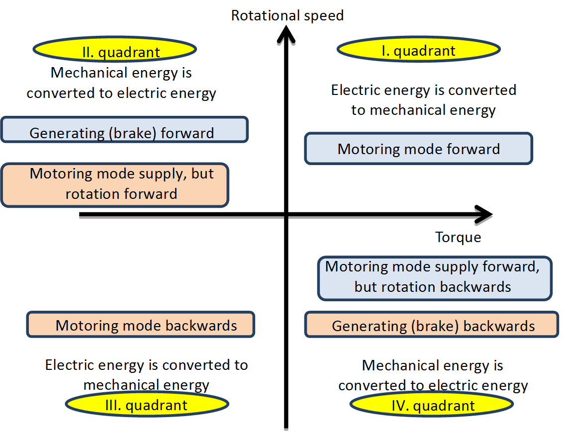
Primarily for DC drives it is an important classification point of view that in which quadrant (see Figure 3-4.) of the rotational speed-torque plain can the electrical drive operate the DC motor.

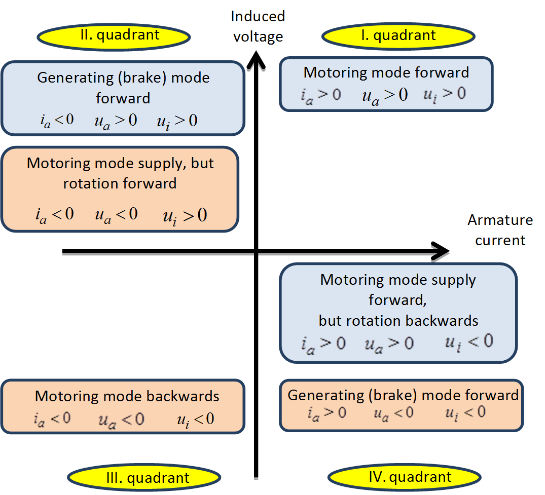
The four quadrants are determined by the direction of the supply voltage and current. Supposing an external excited DC motor let be the armature voltage, be the armature current and be the induced voltage of the armature winding. The signs of the current and voltages in the quadrants of Figure 3-4. can be seen in Figure 3-5.

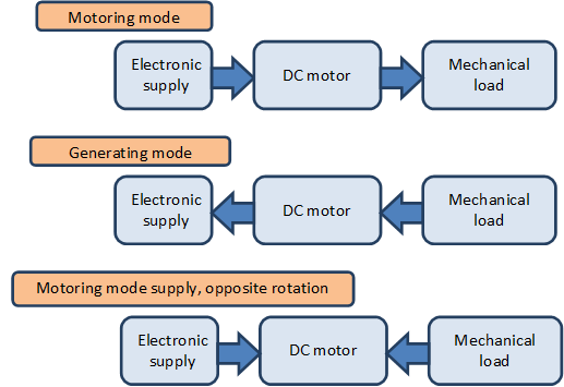
In motoring mode the directions of the voltage and the current are the same, the motor is consuming power from the electrical network (electric energy is converted to mechanical energy). The motoring mode needed for the rotating the motor forward and backwards can be found in the I. and III. quadrants. If for some reason the direction of the current changes then in any case the sign of the generated torque will also change. If the directions of the voltage and the current are the opposite of each other, then the electrical network will take up power (mechanical energy is converted to electric energy). This is called generating (brake) mode and can be realized in the II. and IV. quadrants. It is important to note that a DC motor can enter in the II. and IV. quadrants such a way that the directions of the voltage and the current are remaining the same (motoring mode), but the direction of motor rotation is changed via an external constraint. The asynchronous motors are also capable of this mode, but the synchronous motors are not. In the II. and IV. quadrants Mechanical energy is converted to electric energy in any case, however in case of the directions of the voltage and the current are the same then the motor will consume power from the electrical network as well. In other words both the electric and mechanical energy will be converted to heat; this means a negative impact for the efficiency of the drive. Resistor should be inserted into the electrical circuit of the rotor outside of the motor, on which the generated heat can be dissipated and to limit the current of the motor (in case of asynchronous AC and DC motors). This mode was necessary in case of a crane or elevator when the load is lowered in the past; because there were no cheap electronics available with generating mode at any rotational speeds. The generating mode can be achieved only at higher speeds than the no-load speed (in case of asynchronous motors above the synchronous speed) in case of DC supplied motor. Electronic control is needed for the manipulation of the supply voltage. In four-quarter servo drives the lowering of weights is done in generating mode regardless of the motor type. The generating mode is ensured by the electronics.
The directions of energy flow in the three different modes can be seen in Figure 3-6.

The rotational speed of an asynchronous motor supplied trough an AC chopper can be changed in a very limited extent. These systems won’t be discussed in this lecture note.
3.2. Four quadrants servo drives
First of all is noted that even for demanding AC drives direct AC-AC converters can be used (see ???
Figure 3-7. ), instead of using AC chopper the transistor matrix converter should be used (thyristor-based cycloconverters aren’t used nowadays). This solution isn’t adopted by the industry, but it can happen that this solution will prove industrially optimal.

Most of the servo drives are operated in all four quadrants and the conversion is done in two steps. First the mains voltage is rectified so will form an internal DC circuit, then with the use of a DC chopper in case of DC motor or with an inverter with changeable frequency in case of AC motor the given motor will be supplied. See in???
Figure 3-8. .

In Figure 3-8. there is only a one way arrow pointing outward from the electrical network box because nowadays this is typical. The most common and cheapest rectifiers are based on diodes and these units cannot feed the energy back into the electrical network. The brake resistor is used for dissipating the energy fed back from the motor. In case of diode-based rectifier the non-sinusoidal power supply means a more significant problem than the one-way energy flow, because these devices are taking up non-sinusoidal current and causing pollution to the electrical network. In many cases the diode-based rectifier is kept in the system but an electrical filter is inserted between the electrical network and the rectifier to minimize the electrical pollution. The sinusoidal current consumption can be achieved with open loop controlled rectifier. These devices are enabling the two-way energy flow and also acting as filters. This solution is not common nowadays, but in the near future it is possible for the industry to adopt the technology.
Only of the voltage or the current can be forced to the motor the other one will develop as a result, thus there are voltage and current source power supplies. The voltage source supply is easier to realize, but the current source supply has more direct relationship with the torque (see chapter 2.1.1), thus making the direct torque control more simpler. In the eighties and nineties were actual industrial applications using the so called current-source inverter (CSI) drive topologies. Nowadays the voltage-source inverter (VSI) drive topologies are dominant. This has technological reasons, but no one knows in which direction the technology will further develop in the future. Also in the eighties and nineties the so called resonant converters and in connection the so called soft-switching have appeared.
Most of the motors can be operated in four-quadrant mode.
The torque of synchronous motors can be positive and negative in both rotating directions, and extends into two quarters. In the former case the motor is in motoring mode, in the latter case the motor is in generating mode. The external excited DC motor and the asynchronous motor can enter in three quadrants at same voltage directions. In motor mode the rotational direction can change itself.
3.2.1. Torque sensing and measurement
In most cases the torque is not measured directly, but it is calculated from other electric parameters. The simplest and most inaccurate method for torque estimation is that the consumed power from the electrical network is calculated from the voltage and current in the internal DC circuit.
|
|
(3.1) |
This method is used in case of DC motors and asynchronous motors also. Especially for the asynchronous drives it is more complex and expensive using a more accurate direct method, which is based on measuring the actual current and voltage of the motor.