Chapter 4. Internet-based Telemanipulation
- 4.1. Abstract
- 4.2. Introduction
- 4.3. General approach of telemanipulation
- 4.4. Master devices as haptic interfaces
- 4.5. Animation of the operator’s hand wearing the sensor glove
- 4.6. Overview of control modes
-
- 4.6.1. Basic Architectures
- 4.6.2. Nonlinear scaling (Virtual coupling impedance)
- 4.6.3. Time delay compensation of internet based telemanipulation
- 4.6.4. Friction compensation for master devices
- 4.7. A complete application example: A handshake via Internet
- 4.8. Conclusions for telemanipulation
- 4.9. References for telemanipulation
4.1. Abstract
The Internet is a very fast evolving new technology, allowing people to electronically connect places that are thousands of miles apart. By combining network technologies with the capabilities of mobile robots, Internet users can discover and physically interact with places far away from them, creating opportunities in resources sharing, remote experimentation and long-distance learning. This paper provides an assessment of the state of art of Internet based control and presents a general approach to internet based telemanipulation. The concept is based on layers. This paper proposes these layers as well as their functions. One of the most important problems of a closed-loop internet-based telemanipulation application is the transmission time delay, which can destabilize the system. Furthermore, when using a computer network for sending data, time delay is not even constant. In this paper the Internet transmission time delay is discussed, various remote control modes for robotic systems are surveyed and an internet-based tele-handshaking as an applications is discussed in details. The task is to realize a handshake between two people at two different corner of the world via Internet.
4.2. Introduction
4.2.1. Brief History of Telemanipulation
In about 1945 the first modern master-slave system teleoperator was developed by Goertz at Argonne National Laboratory (ANL) [1]. This system, which was a mechanical pantograph mechanic system, allowed a human operator to manipulate radioactive materials in a “hot cell” from outside. By using a master handle, the human operator could move the slave tong located inside the hot cell and receive force reflection. Soon (in 1954) electrical servomechanisms replaced the direct mechanical master-slave system and able linkages [2]. Closed circuit television was introduced so that the operator could stay at an arbitrary distant place. In addition, the contact force between the slave and its environment was returned to the master arm. In 1964, Mosher developed an impressive work, which was a handy-man containing electrohydraulic arms. Each arm had ten DOF in each arm. The problem of remote control of robotic systems has been the subject of much research in recent years. Remote control of robotic systems has been applied in manufacturing, underwater manipulation, storage tank inspection, nuclear power plant maintenance, space exploration, etc. See en excellent review of relevant historical development in telemanipulation (telerobotics) in [1].
4.2.2. What is Telemanipulation
Telemanipulation is a process where the operator has some task done at the remote hazardous or inaccessible environment as space, underwater, nuclear plants, where he/she cannot physically be. A teleoperator system extends the operator’s capability to be able to work at the Remote Workplace. This extension is achieved by a master-slave system. Telemanipulation is divided into two strongly coupled processes. One process is the interaction between the operator and the master device, the other is the interaction between the slave device and the remote environment contact. The master device represents the distant environment at the operator site, and the slave device represents the operator at the remote site. When humans use this device only to move objects and the reaction force from the distant environment has no significant effect on the performance, than measurement of the operator’s position and visual feedback may be enough. However, if such tasks are to be performed when the reaction of the environment is important and the salve device can do damage in the remote environment for example when screwing a bolt or assembling something, then a force feedback is needed to improve efficiency. Force feedback increases the feeling of being there. The information flow between the operator and remote site can be seen in 4-1. ábra (adapted from [3]), where only three types of information are feedback: visual, audio and sense of touch. A human being receives five types of sensing from his/her surrounding environment but only some of these senses are used during telemanipulation.
![Information streams of the Telemanipulation (adapted from [3])](images/image_29.png)
The structure of this paper is as follows. The next section overviews the general approach of telemanipulation. It introduces three main layers of a telemanipulation system. Section 3 summarizes the basic type of master devices. Section 4 provides a short introduction into control modes used for telemanipulation. Section 5 is an application example of a handshaking via Internet.
4.3. General approach of telemanipulation
4.3.1. Basic definitions
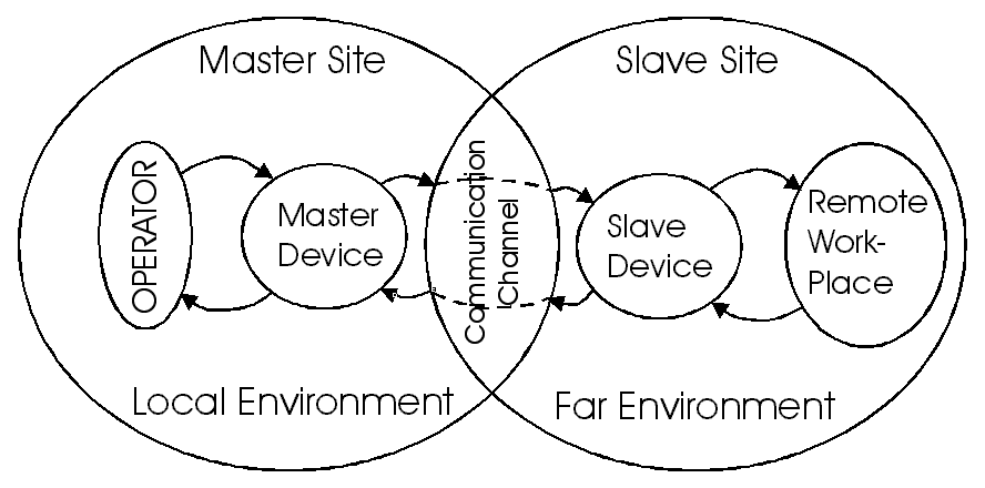
4-2. ábra shows the general concept of telemanipulation. The “world” is divided into two sets: the Master Site and the Slave Site. The master-slave system is realized as two information channels: Action and Reaction channel. The Action channel transfers the information from the operator to the Remote Workplace. The Reaction channel transfers the information to the opposite direction: from the Remote Workplace to the Operator. In the early days of telemanipulation, the human operator’s hands and the remote environment were mechanically coupled. The information was transferred mechanically, that limited the type of the tasks, which they could perform. Nowadays, the information is transferred electrically, that opened a new dimension at the slave side. A Human-Robot System may be considered as a type of telemanipulation, where a human and a robot work simultaneously together to achieve a task. For example, in the case of remotely deactivating of a bomb, the robot must reach the bomb and than the timer must be disassembled with the help of a pair of slave manipulators. In this example the navigation and manipulation tasks may be separated. When a group of mobile robots move a large object cooperatively the operator must control the overall action. In general, the Slave Device can be a Multi Robot System as well, where more than one robot are working together to achieve a task. Computer Networked Control enables systems to be distributed. The concept of an operator and robot can be replaced with some combination of multiple operators, multiple robots, and maybe even multiple assistant agents that work together in a cooperative environment [4]. The Human-Robot type of telemanipulation can be classified into
-
Single master-- single slave
-
Multi-master-- single slave
-
Single master -- multi-slave
-
Multi-master-- multi-slave
We can conclude that the meaning of telemanipulation has extended, and new terminologies have appeared. Some of them collected here.
Teleoperator is the machine itself, which can perform the task in a distant place. Using a general sense of teleoperator, Telerobot is a subclass of it. Originally, telemanipulation means the action in which a slave manipulator tracks the motion of master manipulator. In this case the salve and master manipulator have the same structure. The extension of this concept means a manipulation in the remote environment with a slave device controlled by a master device moved by a human operator. Using this extended meaning, the structure of master and slave device can be different but the whole manipulation process is controlled by the human operator, i.e. the slave side has no own intelligence. The next step is the distribution of intelligence. The slave device may learn the behavior of a human operator and may follow the learned behavior during the period when the command is delayed because of the latency caused by Internet communication [5]. Some authors use the word of teleoperation for the extended meaning of telemanipulaton, some authors use “telemanipulation” and “teleoperation” in the same sense.
A human operator needs the illusion of direct contact with the remote environment to perform fine task such as tele-surgery or remote assembling (disassembling) fine mechanism (timer bomb). A human operator receives five types of sensing (sight, hearing, touch, smell, taste) but the combinations of the first three are used during a manipulation. The psychological feeling of “being there” in an environment based on a technologically founded immersion environment called as Telepresence [6,7], which is should provide the ideal sensation, i.e. we get the necessary information fed back from the slave to the master side in a natural way to have the feeling of being physically at the distant location. Telepresence systems are a subclass of teleoperators. The technology of audio-visual feedback is well developed and available nowadays. The main challenge is the haptic feedback, which is necessary to feel the physical contact with the environment. It is an extension of force feedback. A human operator has different types of receptors for sensing different types of contact forces. Tactile (cutaneous) feedback is sensed by mechanoreceptive nerve endings in the glabrous skin (especially in the finger tips). Its bandwidth is about 50-350 Hz [8]. It provides information of small-scale details, for examples that of the type of surface. The force (kinesthetic) feedback has lower bandwidth (up to 10 Hz) sensed by receptors on the muscle tendon and in skeletal system. It provides information related to body posture. Force feedback not only increases efficiency, but it helps to filter the smaller imprecision of the operator.
4.3.2. Ideal Telepresence
In a typical telepresence, information about task at the remote site is required to help a human operator to feel as if he/she physically is present at the remote place. Accordingly a teleoperator must provide complete transparency, which means the positions, velocities, and forces of the master and slave device are equal. An example of simple remote device is a remote plier used to handle objects in a nuclear plant [5]. If this plier is stiff and easy to move, the operator simply performs the task. Images of the ideal connection between the master and slave for revolute motion and linear motion are shown in REF _Ref364272027 \h (a) and (b). If the operator rotates (move) the master stick by qm (xm) the motion of the slave stick must be the same (qm= qs or xm= xs) and the operator must sense the reaction force of the environment (Fo=- Fe), in ideal case. From this example, the aimed dynamic behavior of the teleoperator is therefore close to a rigid rod which mechanical properties are minimal inertia and maximal stiffness. The connection of the master and slave arms should have 0 mass with stiffness.
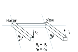
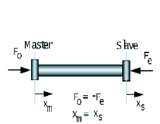
However our work deals with a teleoperator with time delay whose master and slave are assumed to be physically equivalent. The ideal responses for the Telemanipulation with time delay are definite and as follows.
The teleoperator must remain stable.
The force that the human operator applies to the master arm is equal to the force reflected from the environment in the steady state. This can help operators to realize force sensation.
The master position is equal to the slave position in the steady state.
4.3.3. Layer Definitions
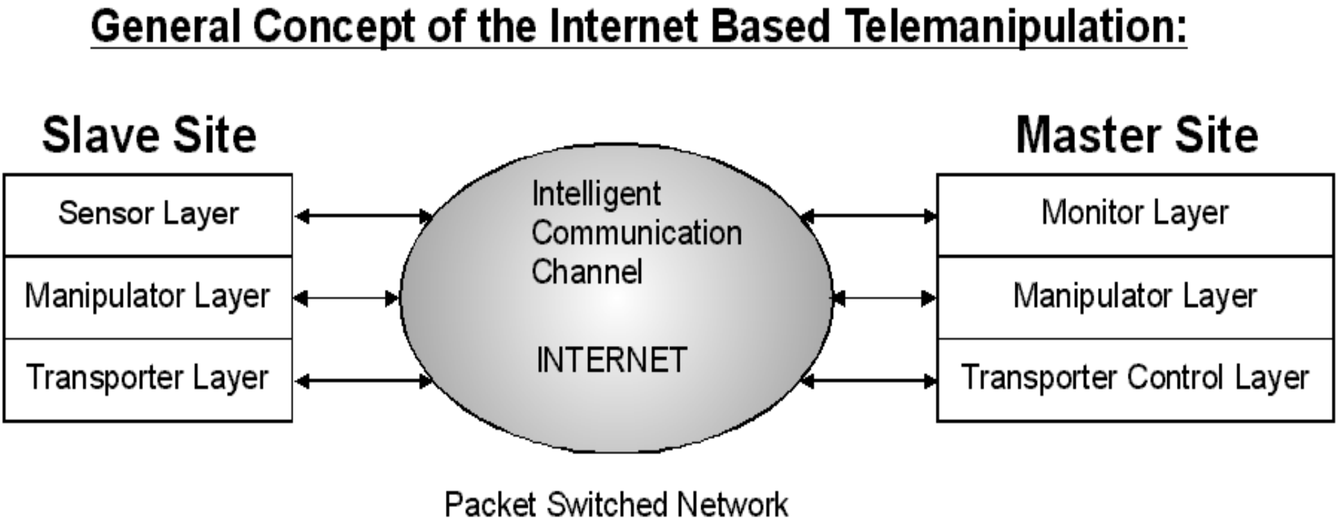
The Master Site and the Slave Site are partitioned to three main layers (see in 4-4. ábra). The layers can communicate vertically with the local layers as well as horizontally with the remote layers via the Internet. The Sensor Layer contains the necessary sensors to observe the Remote Environment, and the Remote Workplace. In general, these sensors are non-contact sensors. The Manipulator Layer makes the effective work in the Remote Workplace. This layer involves the Slave Device typically. This layer may contain contact sensors. The Transporter Layer includes a Transporter (mobile unit), which can carry the slave device. The Monitor Layer at the Master Site shows the processed data of the Sensor Layer. These monitors are usually non-contact displays or indicators. The Manipulator Layer has a real contact with the Operator. This layer involves the Master Device typically. This layer, included with the Master Device, may contain contact sensors, and contact actuators. The contact actuators relay the sensed data of the contact sensors of the Manipulator Layer. The Transporter Control Layer controls the Transporter at the Slave Site. This layer may contain services that can help to the navigation of the Transporter Layer at the Slave Site.
4.3.4. Sensor layer
The configuration of the Sensor Layer can be seen in 4-5. ábra. The non-contact sensors on the Slave Site are observing the Far Environment. The Intelligent Sensed Data Computing System at the Slave Site is a preprocessor for the sensed data. The purpose of this device is filtering, correction and compression. The audio and video compression formats are widely used on the Internet, to decrease the necessary bandwidth. The Computing System may contain a pattern recognition module to improve the efficiency and intelligence of the Slave Site. The purpose of the Intelligent Sensed Data Computing System at the Master Side is data decompression and recovery of lost data.

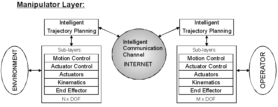
4.3.5. Manipulator layer
There is another approach for the telemanipulation. The process of the telemanipulation can be partitioned into two coupled sub-processes. One sub-process is running in the Local Environment: Local Process. The other sub-process is running in the Remote Environment: Remote Process. The Local Process is the information circulation between the Operator and the Master Device. The Distant Process is the information circulation between the Slave Device and the Remote Environment. If telemanipulation is ideal, the two processes are the same. In case of ideal telemanipulation, the Master Device represents the Remote Workplace in the Local Environment and the Slave Device represents the Operator in the Far Environment. The Communication Channel is the coupler between the two sub-processes. The main task of the Communication Channel is to ensure total transparency in case of ideal telemanipulation.
The configuration of the Manipulator Layer can be seen on 4-6. ábra. Typically, this layer includes the Slave and the Master device, as it is mentioned above. The main purpose of this layer is the position control and the force-feedback. The force-feedback is an information flow between the layers and between the Master and Slave Site. The force- feedback is a typical action-reaction process. The exact realization of the force-feedback depends on the specific approach. The configuration of the Master Device is not equal to the configuration of the Slave Device in a general case. The main purpose of the Intelligent Path Planning is to couple the master and the slave in position and force.
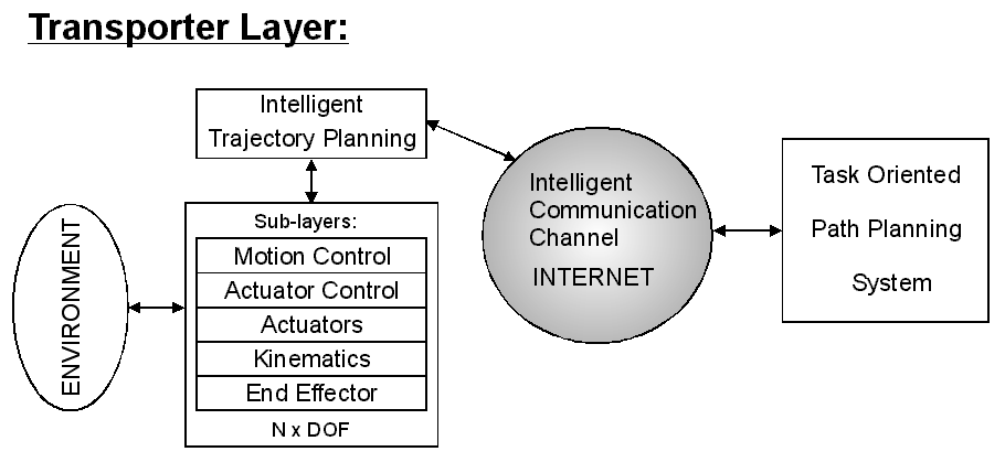
4.3.6. Transporter layer
The configuration of the Transporter Layer can be seen in 4-7. ábra. The configuration of the Slave Site of Transporter Layer is very similar to one side of the Manipulator layer. The Transporter Layer has connection with the Far Environment. The Transporter Layer carries the Slave Device and the necessary sensors.
The Task Oriented Path Planning System controls the transporter on the Slave Side. This device may use advanced services for navigation such as Global Positioning System (GPS), Geographic Information System (GIS) and Intelligent Transport System (ITS).
4.3.7. Special types of telemanipulation
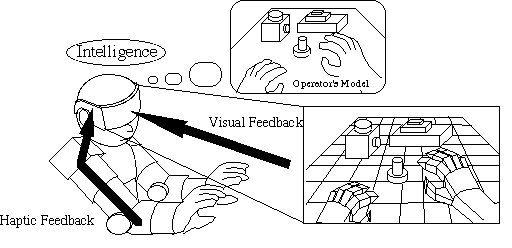
Telemanipulation in virtual reality is beneficial when an operator is learning to perform dangerous or difficult tasks such as working with radioactive materials or disassembling explosives; or driving an airplane, helicopter or submarine in a real time simulator. In addition “Flight and other vehicles simulators” are very popular in the field of entertainment. It can be a very attractive target in both main fields professional and commercial. Telemanipulation in a virtual reality application is shown on 4-8. ábra. The operator wears a head-mounted device that provides visual feedback and an arm and glove type master device giving tactical sensation. The operator can see the visual objects and can touch and move them [10].
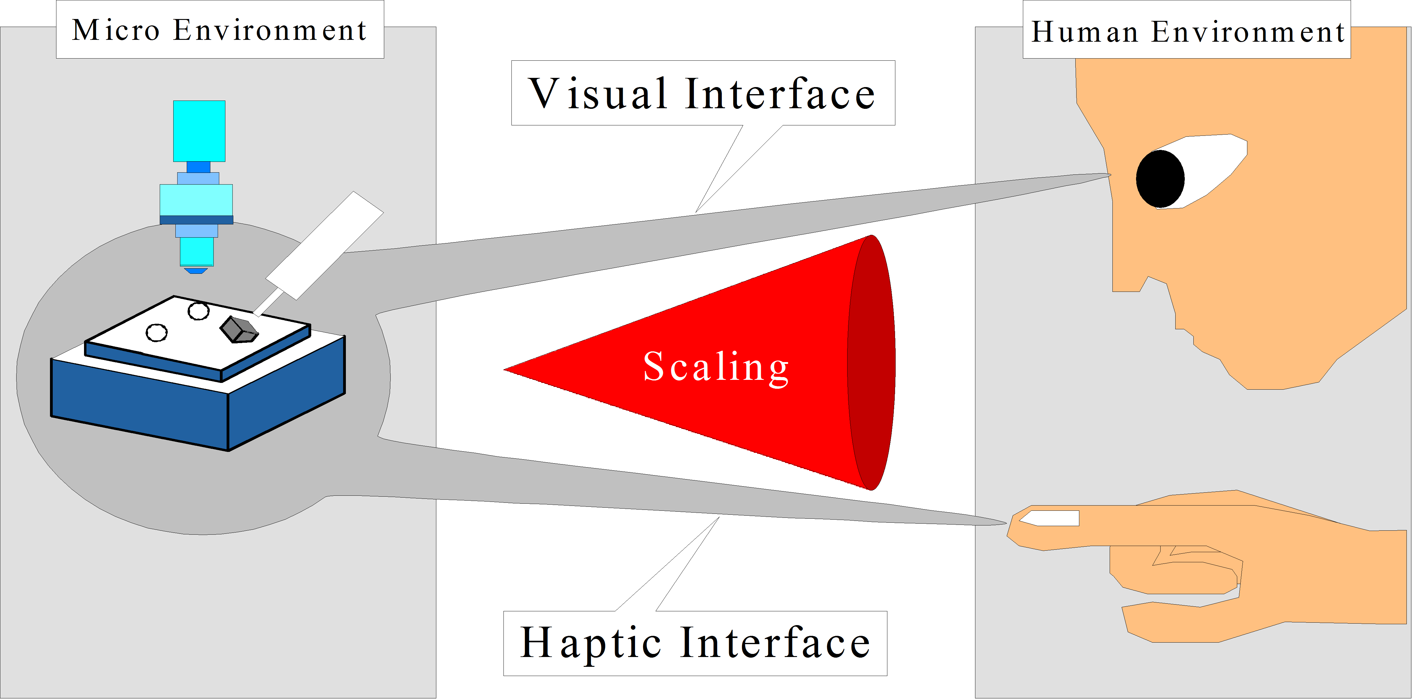
Micro- and nano-technology opened a relatively new, emerging dimension in the field of telemanipulation. Going from macro to micro/nano world, the main phenomenon is the reduction of the size of objects where the effect of length change is defined as scaling. It is obvious that Force and position must be scaled (see in 4-9. ábra). There is another problem called as bandwidth effect, that means bandwidths of the master device including human operator’s reaction and slave device including nano/micro environment are different. The micro/nano actuator has a smaller time constant than the macro force feedback device. So an impedance scaling is necessary to avoid instabilities and unreliable force feeling. It can be considered as a kind of time scaling. In another words, the micro/nano phenomena might be to fast for a human sensation and it must be slowed down by virtual coupling impedance. [11]
4.4. Master devices as haptic interfaces
Human operators perform their tasks mostly by hand and the master device must fit the operator’s hand. In the field of telemanipulation, many haptic devices have been developed. The applications of the haptic devices cover various fields, such as medical application, working in nuclear power plants and entertainment. In this section four important master device concepts are presented.
4.4.1. Joystick with force feedback
It was developed in the early stage of telemanipulation. Nowadays several commercial joysticks with force feedback are available. This device is optimal for low quality telemanipulation application. This device is optimal for "pick and place" operation. Joystick with force feedback is very popular in recent video game systems. Another important application area is the real time simulators of vehicles, such as airplanes, helicopters, and submarines. The main problem with these devices is the dynamics change "on the fly". An additional device is needed for balancing the dynamics of the joystick. This feature is necessary in application where different precision operations are required. Another disadvantage of the device is the two controlled degrees of freedom.
4.4.2. The point type master device
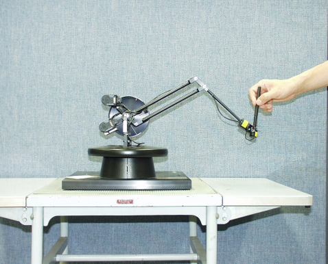
It similar to a six DOF manipulator. The operator can point at the remote site. The Phantom [12] is a point type device (see 4-10. ábra) using direct drive and is noted for its high resolution. However it can cover only fingertips. The operator can control a tip type slave device with this device. Tip type slave systems are widely used in surface manipulation applications, such as telemanipulation in the nano space [11].
4.4.3. The arm type master devices
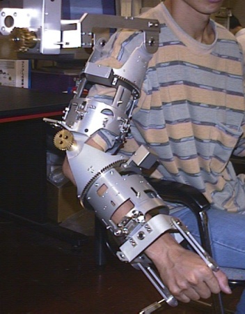
It covers the human arm from shoulder to wrist (see in in 4-11. ábra). It has 6 degrees of freedom. The arm type haptic device is useful in applications where the operator uses his arm to do some task in the remote environment, for example some mining workplace. In several applications the arm type master device is a subsystem of a complex master device.
4.4.4. The glove type master device
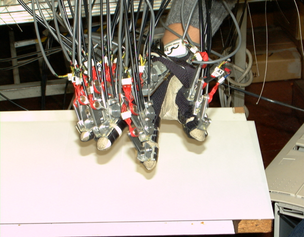
It allows the most complex and dexterous manipulation [13]. The human hand is the most widely used tool. The final goal is to make such a device that the operator can feel as if the function of whole his hand were expanded. Several types of manipulation cannot be performed without force feedback. A 20 DOF sensor glove type device with force feedback (see in 4-12. ábra) is discussed in the next section.
4.4.4.1. Mechanical structure
The wrist location is measured by an inductive sensor. The sensor glove is equipped with force feedback capability to each joint of the operator fingers, so the operator can feel the remote environment as he/she is there. The mechanical structure of a finger is shown in 4-13. ábra. The device is designed with consideration to the space for sensors and actuators. The device is attached to a human hand by bands. A fixed base for all movements of the glove is constructed on a metallic plate fixed on the back of human palm. Five yawing drive units are fixed in the plate. Three pitching drive components are placed on the yawing drive units.
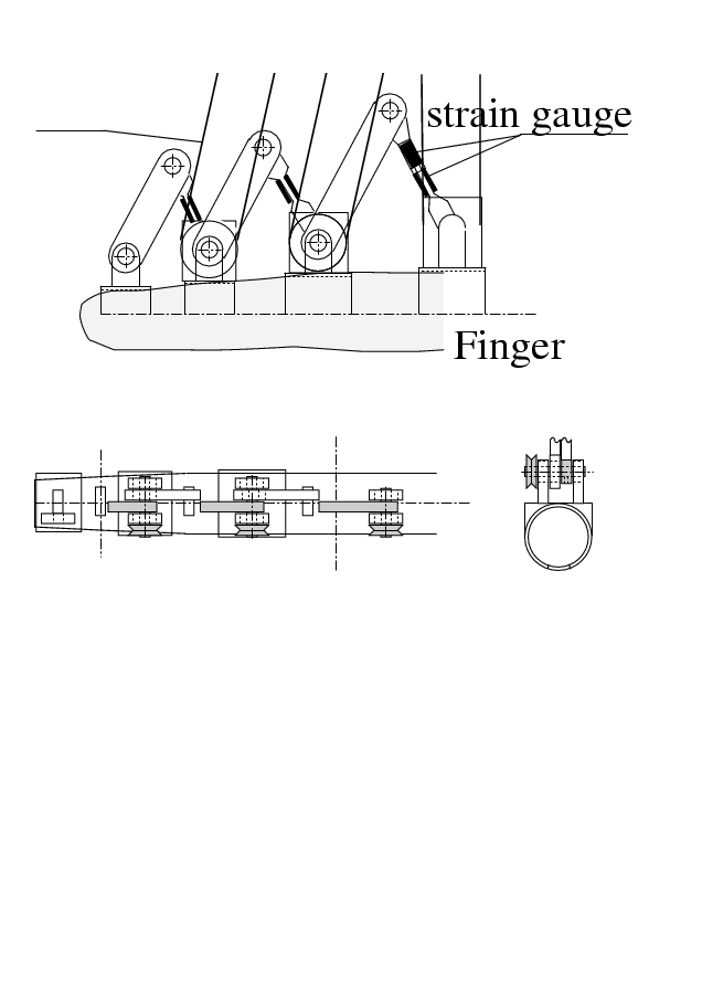
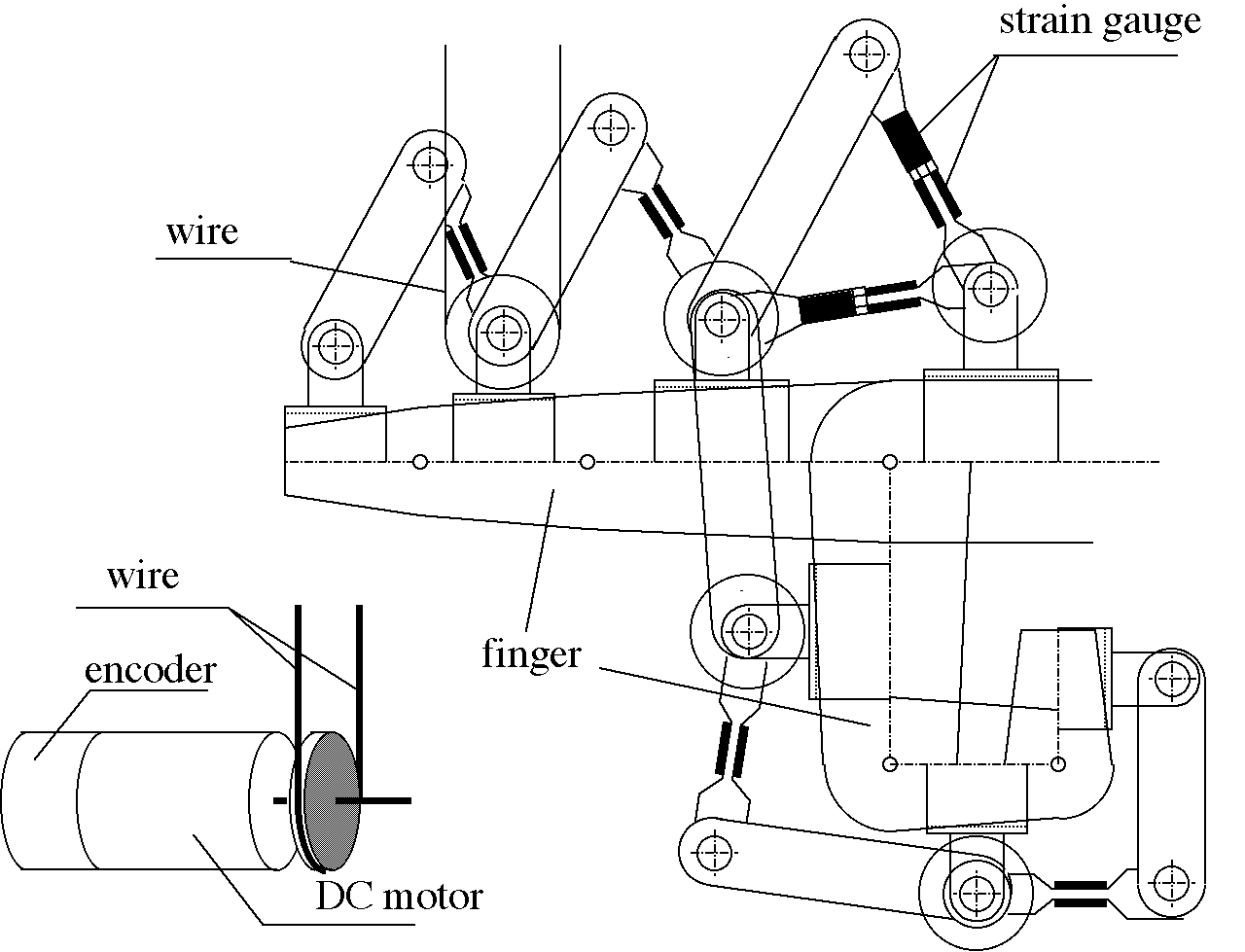
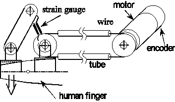
4-15. ábra shows the structure of one D.O.F. of the device. The torques of the finger joints are measured by strain gauges. Rotary encoders in the motors are used to measure the angles of the joints. Ideally, the motors move the joints directly, however, there was no motor available which was small and light enough to be attached on the hand. The pulleys and wires in tubes are used to transmit forces to the motors. Single motors can control all the 20 joints of a human hand independently. One joint of the finger corresponds to 2 links of the device. The main problem is the friction. Because of this additional force, the operator cannot feel, which force is emerged in remote environment. The friction compensation is discussed in Session IV.
4.4.5. Micromanipulation Systems
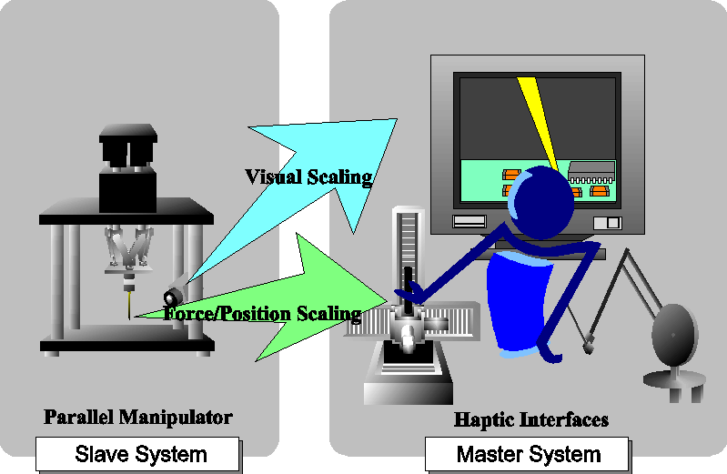
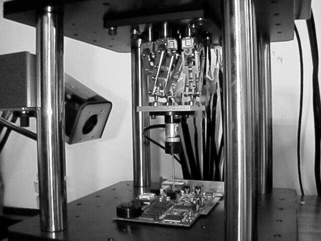
In this section, the tele-micromanipulation system is introduced (see 4-16. ábra). In micromanipulation, visual information of microenvironment is usually fed back by microscope. It is difficult to manipulate micro object using only 2D visual information that is why a 3D animation of slave device (see left part of 4-16. ábra) helps the operator. In this system, the master input device used by the human operator is called as haptic interface, which is a 6 DOF joystick type master device (see in 4-17. ábra). The slave manipulators used directly to perform manipulation tasks are shown in 4-18. ábra. The slave manipulator and master device systems are connected using Ethernet and they are used to perform teleoperation through the network.
4.4.5.1. The Master Device of the micromanipulation system
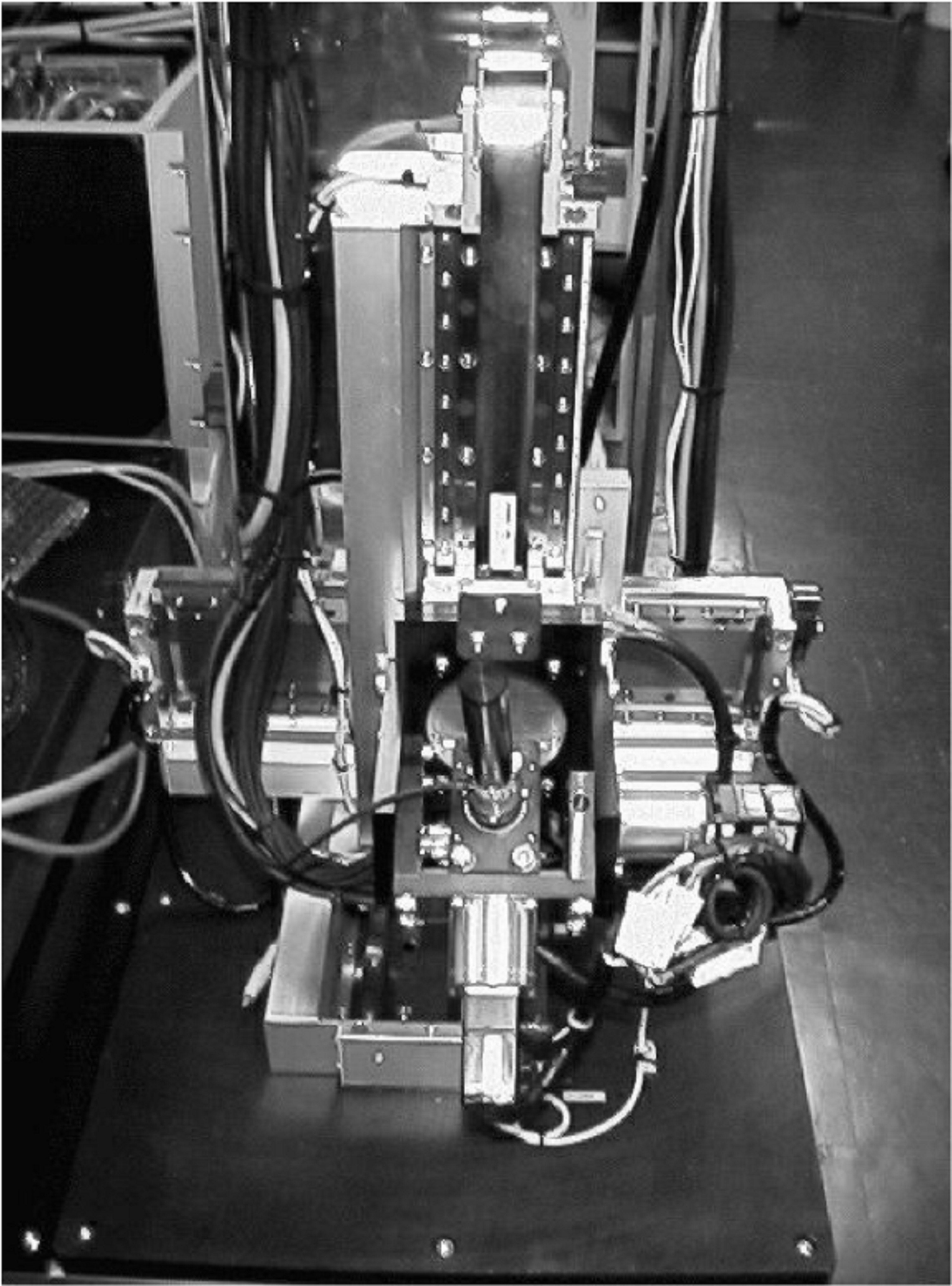
The structure of master device is ought to be same as the slave device. However the parallel link structure has small workspace, which is not convenient for the human operator. That is why a serial link structure is applied to get large workspace, although it decreases accuracy and stiffness. The master device is stick-type device composed of 3 linear servo motors which realize 3 axis (X, Y, Z) parallel movement and 3 AC servo motors which realize rotation around each axis (, , ) [12] (see 4-17. ábra). It covers all 6 degrees of freedom of the slave device. The operator holds the master-stick in his hand and he can move and rotate it. The workspace is 340mmx340mmx340mm for linear movement, and the possible rotation is +/- 15 degrees for each axis. All degrees of freedom have force feedback.
4.4.5.2. The Slave Device of the micromanipulation system
As a slave device, a parallel link manipulator [13, 14, 15] was developed (see in 4-18. ábra), which has 6 degrees of freedom. In general, the parallel link structure has good features of precision and stiffness, although it has small workspace. This structure is fit for precise manipulation. It has 3 degrees of freedom for XYZ linear motion and 3 degrees of freedom for rotation of each axis. Its workspace is almost 30mmX30mmX30mm for linear motion and +/- 15 degrees for rotation. The positioning accuracy is 10 m. It is different from the well-known Stewart Platform structure [15], it has novel structure: Six links, which sprouted verticality from base table can expand and contract. Each two links of six links are combined into one by sublink. Ultimately, the end effector table is held by total 3 points (details in [13]). This manipulator is controlled by a PC (dual Pentium III 500MHz). Operating System is Real Time Linux (RT-Linux) in order to perform motor control with 2.5 kHz sampling time. Input-output using motor, rotary encoder, force sensor are performed by AD, DA, counter, DIO boards connected to an extended bus. As actuators, six AC servomotors of the same type are installed, and 1mm pitch ball screws are connected to each motor. The main drawback of this structure is the complex kinematics and dynamics with singular points as discussed in [13].
4.5. Animation of the operator’s hand wearing the sensor glove
Visual feedback is aimed at giving a quite real representation of the operator’s hand, and the program enables the user to wander it in full three-dimensional space.
The program was designed to run either locally in full simulation mode or over TCP/IP connection, such as Internet or Local Area Network. In simulation mode, the program can be used to represent all the motions of the human hand. To accomplish it, both anatomical and mathematical models were built up, and these models were implemented in OpenGL. The mathematical deduction uses the Denavit-Hartenberg notation, because it can be quite well applied both for hands and in OpenGL. The model uses several basic assumptions, these are:
-
The base coordinate frame is the same for all fingers. This is used for having a completely general case, where the fingertip coordinates are calculated with respect to a common frame of the wrist.
-
This common frame is considered to be at joint 0. This joint is used in order to have the possibility to extend the model at a later time if needed.
-
One finger contains three joints, the first has two degrees of freedom, the other two have only one, which means planar rotation. The position of the first joint is determined by a variable l0 ,which is the distance between the first, common coordinate frame and the first joint.
-
Along one finger, the value of diis 0, which means that the common normal line on the same line.
-
Along one finger the value of ai is the length of the link.
-
The twist angle is taken into account only at the base coordinate frame and at the first joint, since lateral movement of the finger is also considered.
It is important that coordinate frame 0 is the same for all fingers, and is a common reference to the whole hand. The individual i angles and l0 variables determine the exact position and orientation of the next frame of the next joint in each finger. Between the two frames di is just equal to the length of the link, l0. Since joint 0 is of the revolute type, q0 is 1 the relationship between the two joints is (4.1).
|
(4.1) |
In (4.1) A01is the 44 homogeneous transformation matrix between the two adjacent joints and Xsare position vectors in the respective coordinate frames.
|
(4.2) |
|
(4.3) |
As it was stated, in this case is 0º, which means that its cosine is 1 and its sine is 0. For the two joints d is taken to be 0 and a is the length of the link. Substituting these values simplifies the previous equation and yields to (4.4).
|
(4.4) |
Now the position and the orientation of the coordinate frame at joint 1 is received, further transformations can be carried out.
Now there is a general formula for calculating the position of the finger tip with reference to the common base coordinate frame. (4.3) shows this, and it is very similar to (4.1). Matrix T contains the position and orientation of the tip in the base coordinate system.
|
(4.5) |
It is useful to state that joint 2 has two transformation matrices and frames because of the two possible axis of rotation.
|
(4.6) |
where X15 is the position vector of the fingertip in its local co-ordinate frame.
The position and orientation of all five fingertips with respect to the common base frame (the wrist), is given by (4.7) as a function of joint angles.
|
(4.7) |
4.5.1. Grasping
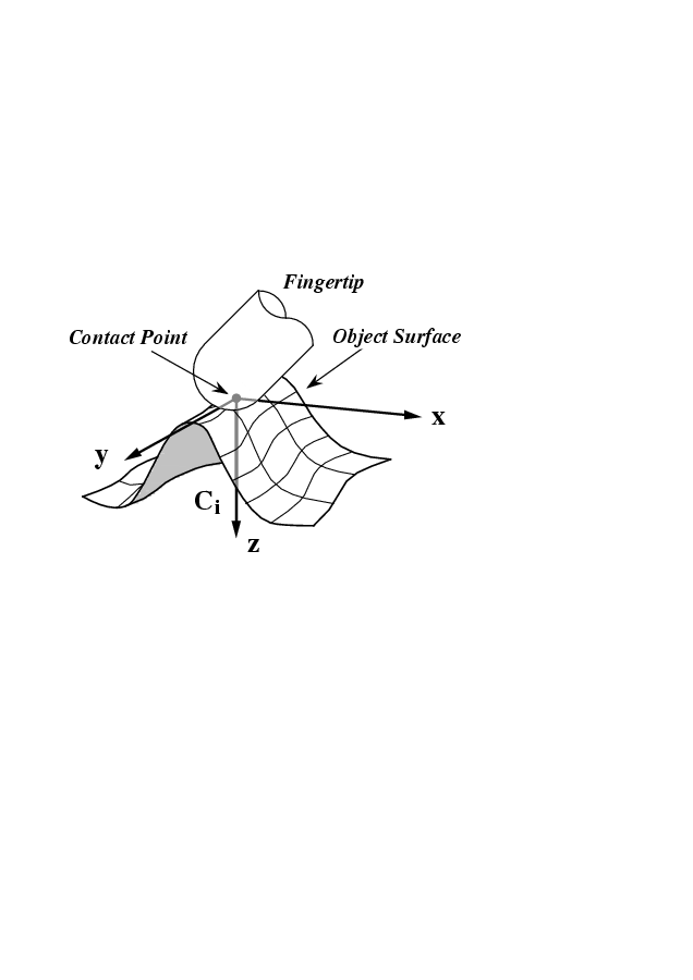
4-20. ábra illustrates the transformations between finger-tip, contact and object coordinate frames [10]. Let us define homogeneous transformation matrices Ui R4x4 and Vi R4x4, where Ui transforms from the finger-tip coordinate frame Ti R4x4 to the contact frame Ci R4x4 and Vi R4x4 from the contact frame to the object frame Bi R4x4.The x- and y-axis of the contact coordinate frame Ci are tangents and the z-axis is perpendicular to the object surface curvature. (4-21. ábra). The transformation matrices i R6x6 and i R6x6 are defined such a way that i transforms finger-tip forces Tifi into forces Cifi in the contact coordinate frame and i transforms these to forces Bfi in the object reference frame B.
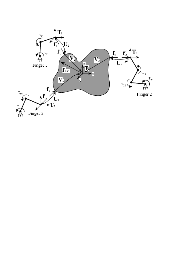
The relationship of coordinate transformations can be written as
|
Ci= Ti Ui B= Ci Vi= Ti Ui Vi Cifi =i Tifi Bfi=i Cifi=i i Tifi |
(4.8) |
where Ui, Vi are homogeneous transformations and i , i are force transformations [10]. The sensor glove has two types of sensor outputs, the torques actuated by the human operator R5x4 and the finger joint angle values R5x4. Ti are calculated from the forward kinematical equations using .
4.6. Overview of control modes
4.6.1. Basic Architectures
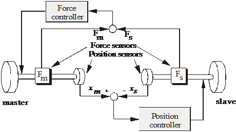
As it seen in 4-2. ábra, the communication takes place in two directions in a telemanipulation system. The controller with two directions for the control commands collectively referred as bilateral controller. Before the electrical master-slave system was developed, in order to realize force reflection, the traditional bilateral controlled master-slave system had been proposed since in 1952 (see in 4-22. ábra) [1] 4-23. ábra shows another traditional control approach for the master-slave system, which was introduced in 1954 [2]. The two position controllers control both the master and slave positions.
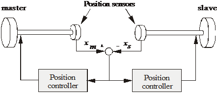
These basic architectures are often used as a starting point to design new controllers. Three main problems and some possible solutions are discussed here.
Nonlinear scaling (Virtual coupling impedance)
Time delay compensation of internet based telemanipulation
Friction compensation of master device
4.6.2. Nonlinear scaling (Virtual coupling impedance)
There are basically two approaches: linear and nonlinear scaling. In the case of linear scaling a single corresponding constant is used between the slave force/position and master force/position:
|
(4.9) |
where xs* and Fs* are the scaled values, p and p are the constants of position and force scale, respectively. In case of nonlinear scaling which is also called impedance scaling [14], forces are scaled independently with respect to their length scaling power relation as follows
|
(4.10) |
Where MV is the virtual mass, DV is the virtual viscosity constant and KV is the virtual stiffness. Note that this scaling method is similar to the concept of virtual impedance, which is widely used in the field of robot manipulators. Impedance scaling improves the performance, especially when the sizes or structures of the master and slave devices are different. The mechanical size has some correlation to its bandwidth. There are certain frequency and amplitude ranges, which are necessary for comfortable manipulation. The reaction force must be transformed into these ranges by the virtual coupling impedance. For example, in case of micro/nano manipulation, the reaction times of the micro/nano actuator and the micro/nano environment may be too fast for human tactile receptors. The reaction force must be slow down i.e. the high frequency components must be shifted to the lower frequency range with the help of virtual coupling impedance. In addition, the virtual coupling impedance behaves as a low pass filter in the communication channel. It can suppress the high frequency components, which can destabilize the system with time delay. In the other hand, it contradicts the requirements of ideal telepresence and transparency. In general, an impedance scaling may help avoiding instabilities and unreliable force feeling but the price, which must be paid for it is the loss of the degree of telepresence and transparency.
4.6.3. Time delay compensation of internet based telemanipulation
The efficiency of telemanipulation has been grown in the last few years. The application of the Internet gives new possibilities to the researcher [15]. The medium for data communication is the Internet in 4-1. ábra. It allows connecting places electronically that are thousands of miles apart. By combining network technologies with the capabilities of mobile robots, Internet users can discover and physically interact with places far away from them, creating opportunities in resources sharing, remote experimentation and long-distance learning. Burgard et al. [16] proposed an interactive museum tour guide robot for guiding the user to visit a museum. Simmons [17] presented an autonomous tour guide robot at Carnegie Mellon University. These tour guide robots have the capabilities of obstacle avoidance, self-referring, and path planning. Web users can control the autonomous robot through a web browser such as Netscape and Microsoft Internet Explorer, and click mouse on a map to assign the desired visiting position. Farzin and Goldberg [18] developed an interactive online lightbox system to provide users with the function of controlling the camera view for captured images. Stein [19] provided web users with a robot arm to paint a picture through a Java™-based user interface. Kosuge et al. [20] proposed the VISIT system using predictive strategy. Hirukawa and Hara [21] constructed a visual model robot arm to assist the teleoperation.
The main problem of Internet based Telemanipulation is the variable time delay. TCP/IP (Transport Control Protocol/Internet Protocol) is mainly used to stream data via Internet. It is a packet switched protocol. This means that the driver divides the data into packets, and sends the packets individually. The receiver tries to collect all the packets and rebuild the original data from the packets. A time delay always occurs when the signal extend from point A to point B. In addition, variable time delay is an immanent characteristic of a packet switched network. Variable time delay has two main reasons. One, the routes of the packets might be different on the network. Second, some packets might be lost. In this case, the receiver asks the driver to send the lost packet again and again. This time delay can destabilize a bilateral teleoperator system. The instability caused by time delay has been revealed by Ferrell [22] as early as 1965. Since that, various approaches for handling the problem of time delay [23] have appeared in the literature, like delay modeling and control system design [24], predictive displays and advanced operator interfaces [25], shared compliance control [26], impedance control [27], or supervisory control [28]. One possible solution for elimination the effect of time delay, namely virtual coupling impedance with position error correction method [29] is discussed in details. This control approach is an extension of the control approach by Otsuka et al [30]. Virtual coupling impedance is applied both at the operator and the remote site. An additional position correction loop is used to synchronize the two distant sites. This control approach is useful to compensate the effect of variable time delay, also appearing on the pocket switched computer network, like TCP/IP.
4.6.3.1. The Smith Predictor
The Smith Predictor is a classical configuration for time delay compensation [31]. Let the P(s) is a first order filter with transportation leg Td. The P0(s) is the model of theplant P(s) in which the time delay is eliminated
|
, |
(4.11) |
There are two loops in 4-24. ábra. In the inner loop, a compensation signal v(t) contains a prediction of y(t). C0(s) is a PID controller.
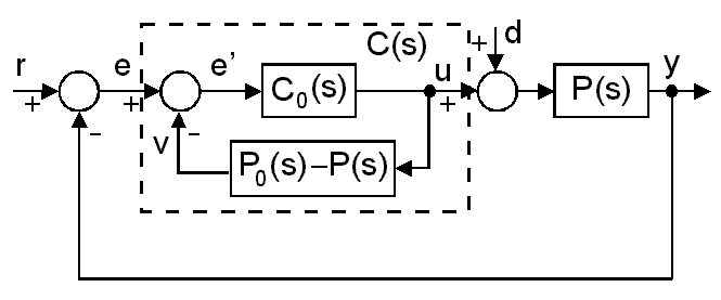
The closed loop transfer function is
|
(4.12) |
Notice, the transcendental term is eliminated in the characteristic equation of the closed loop transfer function. In practice, the perfect model P(s) is not known i.e. perfect elimination impossible, but the Smith predictor reduces the effect of time delay.
4.6.3.2. Wave variable approach
This approach is based on the passivity theory [32], which has close relationship to the Lyapunov stability. The passivity formalism represents a mathematical description of the intuitive physical concepts of power and energy. The basic idea behind passivity is to limit the input power flow such that it does not exceed the output power flow. If the power dissipation is zero, the system is called lossless. In case of a simplified telemanipulation, the operator moves a master device and its velocity vm is transmitted to the slave device, which is forced to follow the master movement, ideally vs= vm. The slave device contacts the remote environment and the reaction force Fs is transmitted back to the operator, who senses Fm=Fs. 4-25. ábra shows a simple telemanipulation with a constant time delay Td in the communication channel, where
|
vs(t)=vm(t-Td) Fm(t)=Fs(t-Td) |
(4.13) |
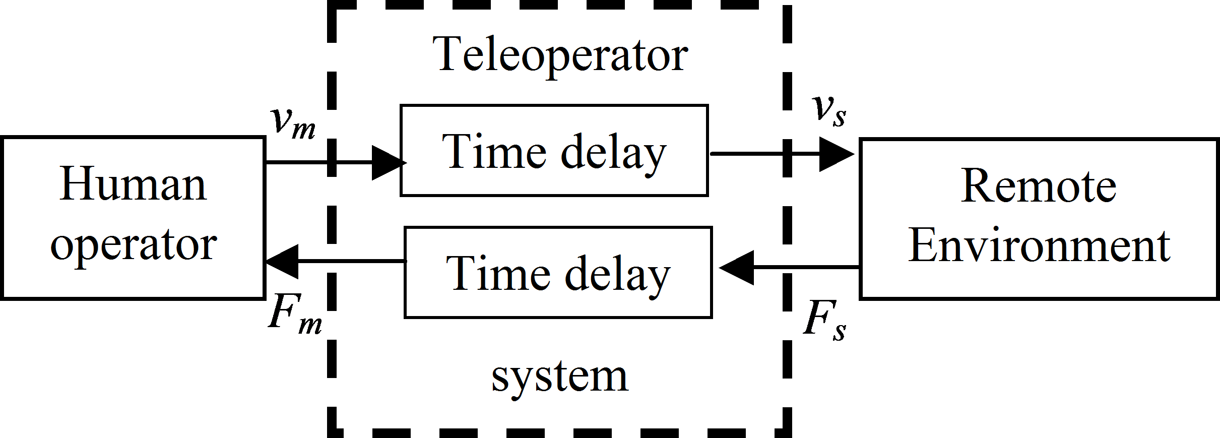
To handle the stability problem caused by the time delay, the bi-directional communication channel is considered as transmission line with a pressure type wave wV(t), a flow rate type wave wI(t) and a power P(x,t)= wV(x,t)wI(x,t), where x indicates that the wave variables must be measured at the same position of the. For stable operation, the transmission line must be passive, the dissipated energy must be non negative.
|
(4.14) |
where Pdiss is the power dissipation.
The trivial selection of wave variables (wI= vm and wV= Fs) does not lead to a passive transmission line. It highlights the source of the original problem. If the master velocity signal is sent and the slave force signal is received via Internet, the time delay may destabilize the operation of the telemanipulation system. To achieve a passive i.e. stable system, the “damping” or “leakage” of the transmission line must be increased. Introducing the following normalized wave transformation proposed in [33]:
|
, |
(4.15) |
the transmission line becomes passive and lossless, which means the dissipated energy is zero. The velocity and force signal is transferred into wave variables before sending and they are retransferred after arriving (see in 4-26. ábra). A possible interpretation of (4.15) is that there are direct feedbacks from the velocity to the force at the master side and from the force to the velocity at the slave side.

Mechanical impedance can be defined in the frequency domain.
|
(4.16) |
According to [36], perfect transparency can be ensured by perfect impedance matching. It can be interpreted as the reflected wave deteriorates the transparency. The terminating impedance of this transmission line includes the characteristics of the remote environment. For ideal transparency the frequency response of the remote environment must be known, and the transmission line has to be modified to mach it in the whole frequency domain. There is no such ideal solution but several papers are published to propose an optimal solution.
4.6.4. Friction compensation for master devices
The main problem is that the mechanism applied as a human interface device usually has a reasonable immanent friction. When the operator moves the master device, the friction might be too big to move it smoothly. Because of this additional force, the operator cannot feel, which force is exerted in remote environment and which force moves the master mechanism. The whole effect of the friction and the whole dynamics of the mechanic construction cannot be eliminated (since it would needed infinite input power) but it can be significantly reduced. The aim of the compensation is to make the system follow an ideal model with small friction. In other words, because of the compensation, the operator feels that it is very easy to move the master device.
The ideal model for a single joint:
|
, |
(4.17) |
where u0 is the input current of the motor, which is proportional to the torque and f is the external torque. The state space variables: [rad] is angle position, [rad/sec] is the angular velocity.
|
, |
(4.18) |
where the subscription “m” and “Δ” refer to the model and the difference between the model and the real parameters.
|
|
(4.19) |
|
, |
(4.20) |
where Jm is the moment of inertia of rotor of DC motor, Dm is viscosity friction constant of DC motor and Km is the torque constant. The observer (model) equation:
|
(4.21) |
Since , the Laplace transform of (4.21) is
|
(4.22) |
If the torques is considered as the input of the system the constant is not necessary. Usually the following simplified, linearized reference model is selected for each degree of freedom of the master device
|
(4.23) |
where torque is the input and velocity is the output signal, Jm is the artificial inertia, Dm is the artificial viscous friction constant. The subscription m refers to the model. Parameters Jm and Dm must be small enough for comfortable manipulation but they must be big enough to avoid the undesirable motion (jitter).
4.6.4.1. Model Reference Adaptive Control based friction compensation
The ideal model with small friction is selected
|
(4.24) |
where is the torque of the motor. The control law of the plant is defined as
|
(4.25) |
, where p is the input gain and q is the feedback gain. The closed loop transfer function is
|
(4.26) |
The closed loop system (4.26) behaves as the reference model (4.24), if
|
and |
(4.27) |
Selecting the following Lyapunov function
|
, |
(4.28) |
where and are the adaptation parameters. The Lyapunov stability criterion guarantees the global stability of the dynamic system (4.26), if is negative semidefinite, which can be ensured be the following adaptive law [17]:
|
|
(4.29) |
4.6.4.2. Sliding mode control based friction compensation
To compensate nonlinear friction force, sliding mode based friction observer will be introduced in this section. Consider the following model with external disturbances and uncertain parameters satisfying the so-called Drazenovic condition, written in the regular state equation form,
|
(4.30) |
where and the bar refers to the nominal or desired (ideal) system matrices. and are the respective uncertain perturbations and f(t)is an unknown, but bounded disturbance with bounded first time derivative with respect to time.
Now is defined as the uncertainties and the disturbance of the system.
|
(4.31) |
The second line of (4.30) can be rewritten by .
|
(4.32) |
According to [34], is estimated by a discontinuous observer:
|
(4.33) |
whereis the discontinuous feedback. The goal of the design to find a feedback signal, denoted, such that the motion of the system (4.30) is restricted to belong the manifoldS.
|
(4.34) |
In sliding mode (),contains information on the system's parametric uncertainties and the external disturbance, which can be used for feedback compensation (compare (4.32) and (4.33)).
The simplest control law, which can lead to sliding mode, is the relay:
|
(4.35) |
If is in the range of B2 ( range (B2)), the ideal sliding mode occurs [35].
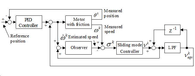
In the practice, there is no way to calculate the equivalent control veq precisely, but it can be estimated by a low pass filter for v as showed in 4-27. ábra. There are two loops in 4-27. ábra. The observer – sliding mode controller loop should be as fast as possible to achieve an ideal sliding mode. This is granted because this loop is realized in a computation engine in the recent application. The real system – compensator (consisting of Sliding Mode Controller and LPF) loop should be faster than the change of the disturbance. On the other hand, the smallest un-modeled resonant frequency of real system should be out of the bandwidth of that loop to avoid chattering.
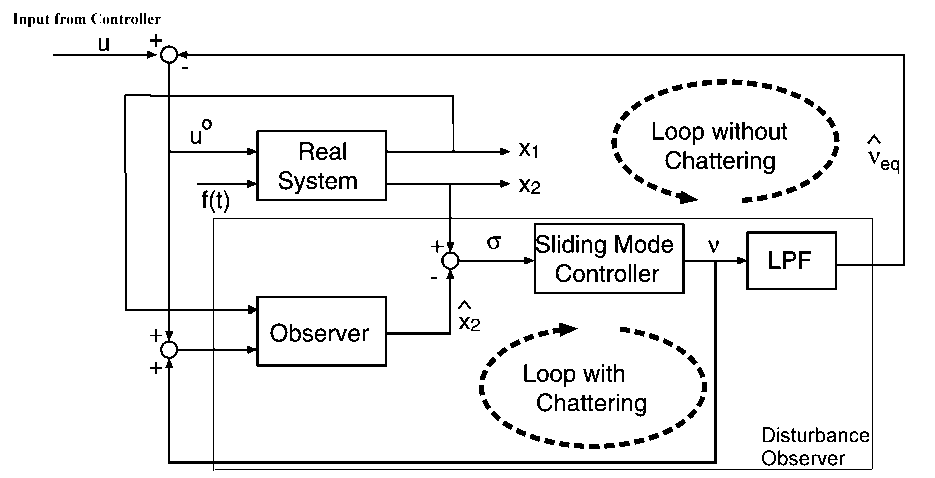
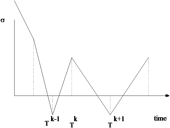
The robustness of continuous time sliding mode control is realized by the high-frequency switching of the discontinuous observer feedback signal . To adapt the sliding mode philosophy for a discrete time observer, the sampling frequency should be increased compared to Lumberger observer. If the switching frequency of the relay (4.35) is not enough high, might chatter around the manifold = 0. as shown in 4-28. , where Tk denotes the time of K-th
sampling. In case of discrete-time observer, the observer feedback signal may switch from +Mi and -Mi and vice versa resulting keq = 0 even if eq 0. The bigger the Miis, the bigger the chattering is. If Mi is smaller than the disturbances, it cannot eliminate the disturbances.
Applying the Lyapunov stability theory, let the positive definite Lyaponov function candidate is chosen in the following form:
|
(4.36) |
The observer feedback is chosen in such a way, that the derivation of the Lyaponov function meet the following condition:
|
(4.37) |
As it was proposed in [6,8], the condition (4.37) is satisfied if
|
, |
(4.38) |
where D is a positive definite matrix.
|
(4.39) |
The observer feedback can be expressed from (4.38)
|
(4.40) |
The first term is responsible for the chattering free reaching of the sliding manifold, but it is 0, if the system in sliding mode. Since is not known, the observer feedback must be estimated.
The discrete-time observer equation:
|
(4.41) |
where the discrete-time observer feedback estimated in the following form:
|
(4.42) |
where , and D'=TD+I. It is noted, that the observer feedback (4.42) does not need additional LPF.
The advantage of this method that it does not need model inversion [16], which was the main problem in case of the inverted model, based disturbance observer.
Applying the above method for friction compensation of a single joint, the parameters are
|
, , . |
(4.43) |
4.6.4.3. Friction Compensation Experience for sensor glove
The test system for tuning of the friction disturbance observer is shown in Fig. 4-29. The input signal of the system is the reference position. This signal is came from the angle sensor of main joint of the index finger. In this experimental three type of control pattern was introduced:
PD type controller without friction compensation
PID type controller without friction compensation and
PD type controller with friction compensation.
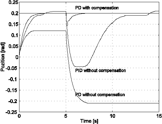
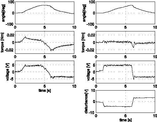
In order to emphasize the compensation capability of the method a simple PD controller is tested, which cannot eliminate the effect of the friction itself. The reference signal is a step change (0.2 rad). The external disturbance is also a step change, added to the motor input voltage but it lags 5s to the reference signal. Its absolute value is very big (12V) since it is equals to the max. input voltage. To avoid the saturation, it has an opposite sign that of the reference signal.
Fig. 4-30 shows the time functions of the reference and the measured positions. It is well known, that the PD controller can not eliminate the steady state error (see Fig. 4-30.). The same PD controller with compensation using disturbance observer can eliminate this error even when there is a quite big friction and load torque (see Fig. 4-30). In case of PID controller, the nonlinear characteristic of the friction causes a limit cycle. These results demonstrate the effectiveness of the sliding mode based disturbance observer, when external disturbance occurs.
The friction compensator provides an additional compensation signal to any conventional closed loop controller and it improves its performance.
4.6.4.3.1. Free motion of the operator's index finger
The overall control system for free motion of the operator's index finger is shown in 4-31. ábra.. The input signal of the PID controller is zero, which means the sensor glove device follows the human hand. Free motion can be considered as a basic behavior of the haptic device. The operator is expected to feel no inertia and to move his finger freely. The friction of the device should be eliminated by control. In free motion, it is assumed that the error between the angle of the device and that of the human finger is detected by the torque sensor. There is a simple torque control loop, with a PID controller. Because of the nonlinear characteristics of the friction, it cannot be tuned well. The additional sliding mode based friction compensation may improve the performance significantly [13].
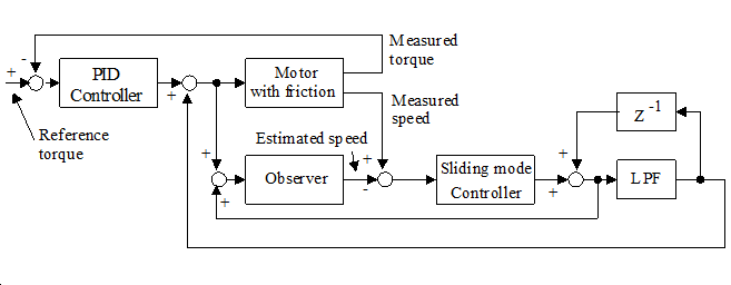
If motor is controlled in such a way that the strain gauge output voltage remains 0, the device follows the movement of the human finger and the operator cannot feel the friction force. Two controllers were compared namely a PID controller and a PID controller with disturbance compensation. The aim of these controllers is to nullify the torque measured by the strain gauge. In this experiment, the operator inserts his/her index finger in the device and moves only the root joint of the finger hand up and down during 10 seconds (see in Fig. 4-32. ábra). The upper plots are the angle of motor. The second graph in Fig. 4-32. ábra. shows the difference of the two methods clearly. The torque of the operator is small if the sliding mode disturbance observer is applied. The average torques of the finger joint are 0.009[Nm] (only PID) and 0.002[Nm] (PID with the sliding mode observer), respectively. Of course, the fatigue of the operator is not linear to the torque, the comforts of the operator significantly improved.
4.6.4.3.2. Virtual wall experiment
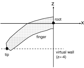
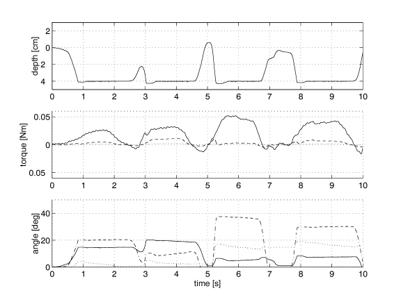
In this experiment the visual feedback is also used, so the first step was done to the telemanipulation. A virtual wall with constant elasticity is defined as in Fig, 4-33. ábra The virtual wall is -40 mm far from the operator’s palm. When the operator’s end of point finger reach the surface of the virtual wall’s position, the actuators of sensor glove give the force to finger. So the operator can feel the surface forces of the virtual wall. The sensor glove is a kind of dynamics interface between the operator, and the virtual reality. The operator four times touch the virtual wall. Each touch has different torque, as can seen on middle part of Fig, 4-33. ábra. The dashed line is the PID controller with disturbance observer, and the countinuous line is also a PID controller, but without disturbance compensation.
4.6.4.3.3. Visual Feedback of the operator
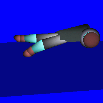
In the virtual wall experiment two computer was connected via memory mapping card. The memory mapping card give a common memory interval for the connected computers to share variables. In this experiment the joint angles and torques was shared between two computers. One computer is an IBM PC which is the computation engine for the sliding mode based disturbance observers for 20 degree of freedom. The other is an Indigo by Silicon Graphics. The challenge of Indigo is the visual interface for the operator. The Indigo contains the virtual reality and a virtual hand, what is like a reflection of the operator’s hand. When the operator moves his/her fingers the angle positions and
torques are shared with the Indigo. The indigo will draw a moving hand according to the operators hand position. When the virtual hand touch the virtual wall, forces interact between the hand and the wall. This forces are the base parameters for the control of sensor glove.
4.6.4.4. Friction Compensation Experience for the micro manipulation system
The whole effect of the friction and the whole dynamics of the mechanic construction cannot be eliminated (since infinite input power would be needed) but it can be significantly reduced. The friction force is measured approximately. In non-compensated case of axes Y, the friction force varied in the range of 20-30 N (see in Table 1).
|
Controller\Axis |
X |
Y |
Z |
|
Without Control |
10 [N] |
32 [N] |
14 [N] |
|
Classical MRAC |
0.05 [N] |
0.07 [N] |
0.05 [N] |
|
Sliding mode based MRAC |
0.001 [N] |
0.002 [N] |
0.005 [N] |
This force is too big for a smooth, comfortable operation. The aim of the compensation is to make the system follow an ideal model with small friction. In other words, because of the compensation, the operator feels that it is very easy to move the master joystick. Some tests were carried out to find when the operator feels the operation easy and comfortable. After these tests, the following linearized reference model is selected:
|
(4.44) |
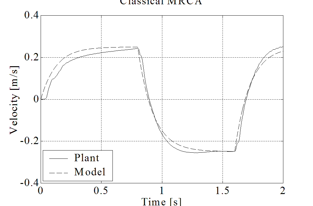
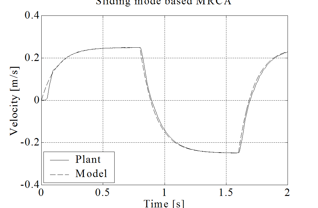
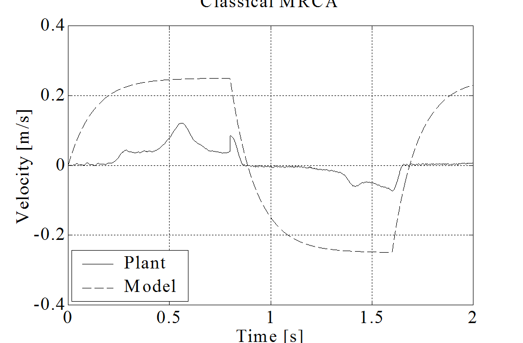
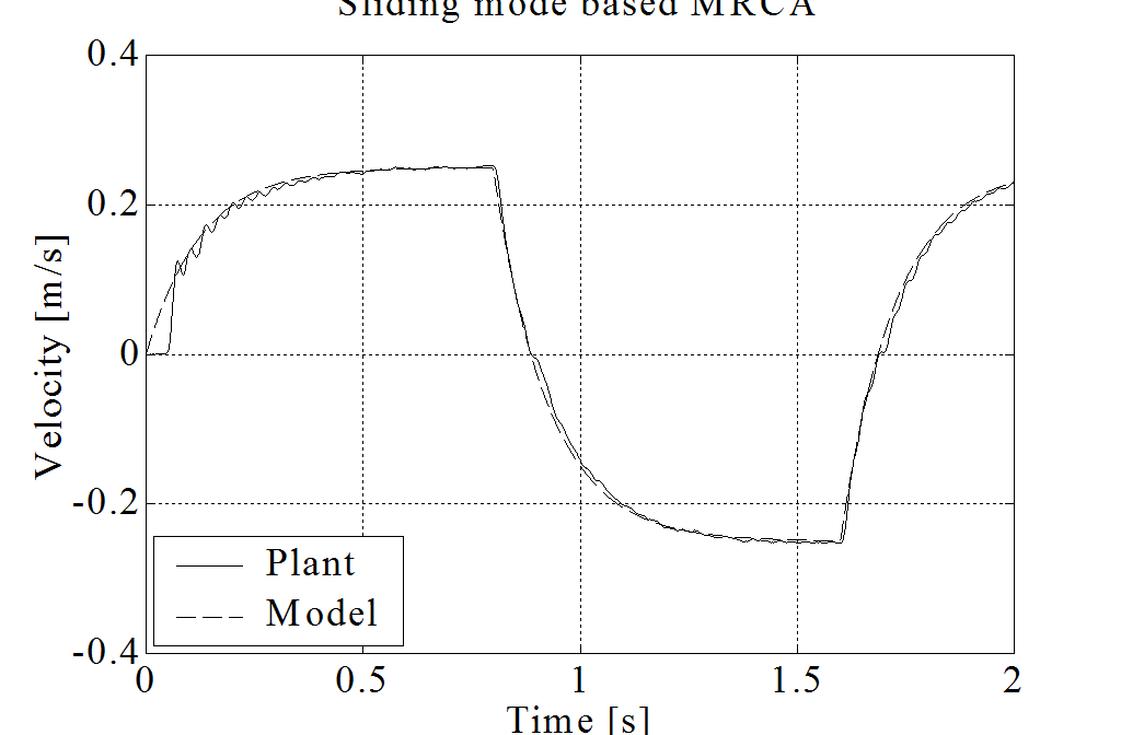
where torque is the input and velocity is the output signal. According to the above model, the “artificial friction force” is only 0.1N with a constant speed of 2.5 m/s. A classical (see in 4-36. figure) and a sliding mode based (see in 4-37. ábra) model reference adaptive control methods are compared. The applications of these methods for friction compensation are published in [7] and [8].
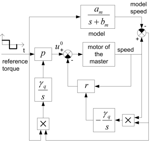
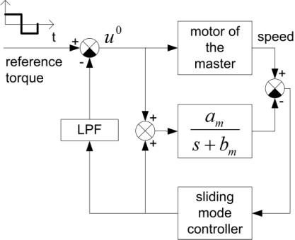
Because of the page limit axis X and Y are examined here. The reference signal is a squared pulse train with 0.1N amplitude and 0.4s period. The measurement results are shown in 4-38. figure and 4-39. figure. The friction of axis Y is significantly bigger. It is difficult to find an optimal adaptation parameter, which ensures fast adaptation but avoids the overcompensation. In overcompensated case, the joystick is moving randomly with 0 reference torque, because of the measurement noise. It is obvious that the bigger adaptation parameter means faster adaptation, but bigger possibility of random movement. The proposed Sliding Mode MRAC method seems to be more robust in our experimental environment.
4.7. A complete application example: A handshake via Internet
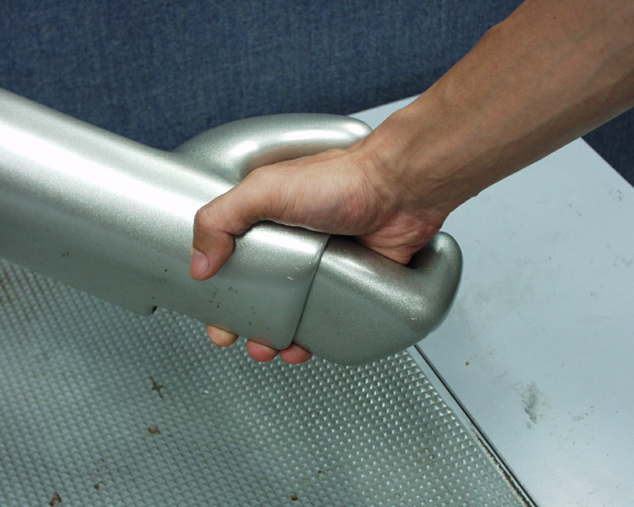
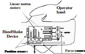
A handshake via Internet is an interesting type of telemanipulation [29]. The task is to realize a handshake between two people at two different corner of the world. Let one be the one the operator and the other the far environment reacting to the operator (hand) movement. The master device will be a hand-shape device in the operator’s hand. The slave device is identical. When the operator grasps the master device (see in REF _Ref364272598 \h a and b), the master device transforms the movement and force to the slave device. The slave device gives this movement to the far environment (the other person’s hand). This person gives a reaction force and a movement to the slave device. This information is transmitted to the operator via master device. The handshake will be realized between two people far from each other. The main challenge is compensation of the time delay.
4.7.1. Virtual Impedance with Position Error Correction
Virtual Impedance with Position Error Correction (VIPEC) is based on the concept of the impedance control. VIPEC is composed of two major parts: a virtual impedance model (VI) and a position error correction part. The virtual impedance model generates a motion trajectory for a manipulator based on input forces and its dynamics. The position error correction part is added to decrease the position difference of the master and slave.
4.7.1.1. A. 1 Virtual Impedance
In the case of a 1 DOF linear motion manipulator, it is assumed that a virtual mass, Mv, is attached to a manipulator arm. This virtual mass is supported by a virtual damper, Dv, and a virtual spring, Kv. The structure of the VI is shown in 4-41. ábra.

When a force is applied to the virtual mass, the position of the virtual mass is modified according to the dynamics of VI. The dynamic equation of VI is as follow.
|
(4.45) |
where F(t) is the force detected at the virtual mass and x(t) is the displacement of the virtual mass. The transfer function of the VI acts as a second order low pass filter to convert force into displacement. Thus the displacement is always smooth even if the force contains high frequency components.
4.7.1.2. Position Error Correction
The structure of a teleoperator with time delay utilizing the VIPEC is illustrated in 4-42. ábra. The PEC part (the shaded part) is added to the original approach [30] in order to improve the response of the teleoperator by reducing the position error between the master and slave positions.
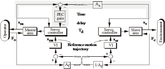
In 4-42. ábra, Fodenotes the force that an operator applies to the master arm, and Fe denotes the reflected force when the slave arm contacts with the environment. xm and xmrdenote the position and the reference position of the master arm. xsand xsr denote the position and the reference position of the slave arm. Td represents a delay time in data transmission between the two sites. Af is a scalar unit, which can be varied depending on the size ratio of the slave and the master.
Each VI generates the reference motion trajectory for each manipulator arm based on the sum of two forces: the force from its own site and the force received from the other site. The data transmission from one site to the other site is delayed by Td . The reference motion trajectory from VI is sent to a servo controller to control the position of the manipulator arm.
The control approach can be used for the master and the slave arms, which are different in size by appropriately adjusting Af and the parameters of each VI. For example, when the slave is a micro robot, which is smaller than the master.
The dynamic equation of VI at the operator site is
|
(4.46) |
The dynamic equation of VI at the remote site is
|
(4.47) |
Without loss of generality, Af =1 and both VIs have the same parameters. When the parameters of VI are appropriately determined, the system should remain stable. In the steady state, Fo is approximately equal to Fe when Kv is set to a low value, and the master and the slave positions should be identical. However, when time delay is present in the teleoperator, the control approach VI without PEC part causes the position error between the master and slave positions, since there is no comparison between these both positions. To reduce this position difference, the PEC part is added in order to make a closed loop system. Therefore the position error can be reduced. The slave position, delayed by Td, is transmitted to the master site and compared to the master position. The difference between the two positions is sent through the PEC gain, and then modifies the reference motion trajectory of the master arm.
Control model of the Handshaking device
4-43. ábra shows the control system diagram of the master-slave system inside the tele-handshaking system with VIPEC approach. The armature inductance, La of each motor is neglected. The two linear motion motors represented by the master block and the slave block can be modeled as simple DC-motors with the transfer function.
|
(4.48) |
where X and Ea are the Laplace transformed of motor shaft displacement and the applied armature voltage, Km is the motor gain constant, Tm is the motor time constant, and Kp is a constant to convert the angular displacement into displacement.
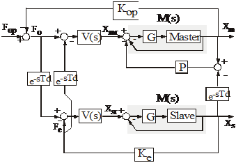
The servo controller is a proportional controller whose gain is G. The closed-loop transfer function of the manipulator arm and the controller is
|
(4.49) |
Gain P represents PEC gain. For simplicity, the environment is modeled by a spring with stiffness constant Ke. Therefore the dynamics of the spring interacting with the slave arm is modeled as follows.
|
Fe (t) = Ke xs(t), |
(4.50) |
where xs is the displacement of the spring. The dynamics of the operator including the dynamic interaction between the operator and the master arm is approximated by
|
(4.51) |
where Fop is the force generated by the operator's muscles. Mop, Bop and Kop denote mass, damper, and stiffness of the operator and the master arm respectively. Similarly to REF _Ref364274698 \h \* MERGEFORMAT , the displacement of the operator in (4.51) is represented by xm since it is also assumed that the operator is firmly grasping the master arm and never releases the master arm during the operation.
4.7.2. Experiment
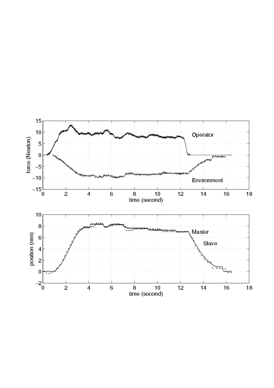
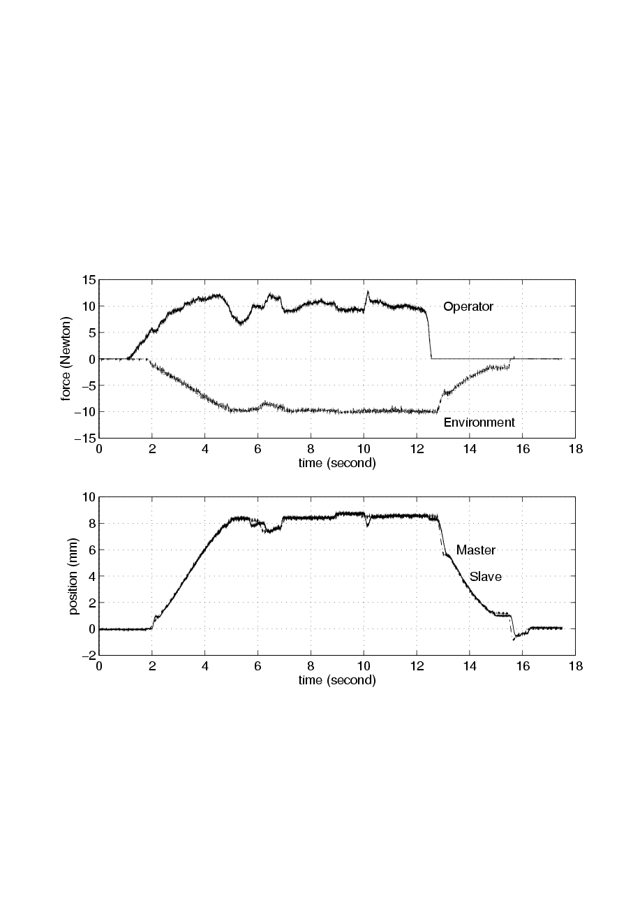
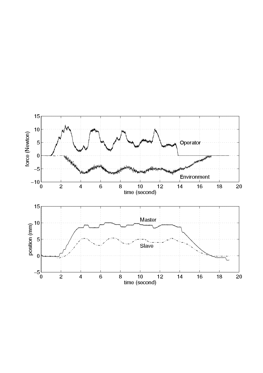
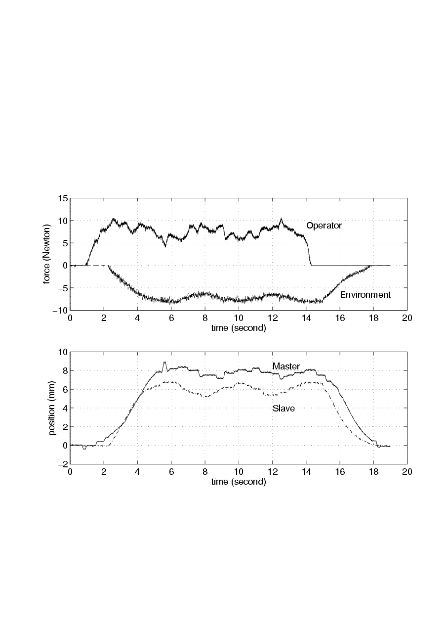
Using the tele-handshake system, two human operators, operator A and operator B, shake hands with each other. When operator A tries to shake the hand of operator B by moving the master arm A, the slave arm A should move the same as the master arm A does. When the slave arm A contacts the palm of operator B, operator B can feel grasping force of operator A. Operator B also can grasp the virtual hand of operator A in the same way. Two operators succeeded to shake hands with each other and achieved force sensation through the tele-handshaking Device. Experimental results of simple VI and VIPEC methods are compared in 4-4. figure and 4-5. figure. In 4-4. figure, the time delay is negligible. The difference between the two methods is not significant. In both cases, the position of master and slave device are approximately the same. 4-5. figure illustrates the experimental results with 400 ms time delay. In both cases, the system is stable and the operators can feel grasping force. However, the position difference between the master and slave device is smaller in case of VIPEC method.
4.8. Conclusions for telemanipulation
The Internet based telemanipulation is a relatively new and attractive research field. It is fruitful ground for applying new and sophisticated control methods to eliminate the time delay and nonlinear friction force, which are the main challenges in this filed. Of course, the total elimination is impossible, but a stable operation may be achieved. This paper presented a promising method, namely Virtual Impedance method with Position Error Correction. The effectiveness of this method has been proved by measurement results of a tele-handshaking device.
4.9. References for telemanipulation
[1] T.B. Sheridan, “Telerobotics” Automatica, Vol. 25, No. 4, pp 487-507, 1989
R. C. Goertz and W. C. Thompson, „Electroically Controlled Manipulator” NUCLEONICS, Vol.12, No. 11, pp. 46-47, 1954.
[2] S. Lee, B. Bekey and A.K. Bejczy, “Computer Control of Space-borne Teleoperators with Sensory Feedback,” Proc. IEEE Int. Conf. On Robotics and Automation}, pp. 204-214, 1985.
[3] Barney Dalton, Ken Taylor: A Framework for Internet Robotics. Proceedings of IEEE/RSJ Int. Conf. on Intelligent Robots and Systems, WS2, pp. 15-22, 1998.
[4] S. Mizik, P. Baranyi, P. Korondi, and M. Sugiyama, “Virtual Training of Vector Function based Guiding Styles” Transactions on AUTOMATIC CONTROL and COMPUTER SCIENCE ISSN 1224/600X vol. 46(60) No.1 pp. 81-86. 2001.
[5] Handlykken M., Turner T., “Control systems analysis and synthesis for a six degree-of-freedom universal force-reflecting hand controller”, In proceedings of the IEEE Conference on Decision and Control, ‘80, vol 2, pp 1197-1205. 1980.
[6] Sheridan, T.B., “Telerobotic, Automation, and Human Supervisory Control” Cambridge, MA: The MIT Press, 1992.
[7] Burdea, G. and Coiffet, P.,“Virtual Reality Technology” New York: John Wiley & Sons, Inc, 1994.
[8] J. Dudragne, C. Andriot, R. Fournier and J. Vuillemey „A generalized bilateral control applied to master-slave manipulators” Proc of 20th Conference of International Society for Intelligent Research, pp. 435-442, 1989.
[9] Y. Kunii and H. Hashimoto, “Dynamic Force Simulator for Multifinger Force Display” IEEE trans. on IE, Volume 43, pp.74-
[10] Metin Sitti, Hideki Hashimoto: Two-Dimensional Fine Particle Positioning Using a Piezoresistive Cantilever as a Micro/Nano-Manipulator. IEEE International Conference on Robotics and Automation, pp. 2729-2735 1999.
[11] Thomas H.Massie, J.Kenneth Salisburg, ``The PhantomHaptic Interface: A Device for Probing Virtual Objects'', Proceedings of the 1994 ASME International Mechanical EngineeringCongress and Exhibition, Chicago, Vol. 55-1, pp.295-302
[12] Péter Korondi, Péter T. Szemes and Hideki Hashimoto, „Sliding Mode Friction Compensation for a 20 DOF Sensor Glove”, Transaction of ASME, Journal of Dynamic Systems, Measurement and Control, ISSN 0022-0434, December 2000, Vol. 122. P. 611-615.
[13] J. E. Colgate: “Robust Impedance shaping telemanipulation”. IEEE Transactions on Robotics and Automation, 9(4):373-384, Aug. 1993.
[14] Ren C. Luo, Tse Min Chen, Chih-Chen Yin: “Intelligent Autonomous Mobile Robot Control through the Internet”. ISIE 2000, Cholula, Puebla, Mexico, 2000 W.
[15] Burgard, A. Cremens, D. Fox, D. Hahnel, G. Lakemeyer, D. Schulz, W. Steiner, S. THRUN: “The Interactive Museum Tour-Guide Robot”. Proceedings of National Conference on Artificial Intelligence, pp. 11-18, 1998
[16] Reid Simmons: “Xavier: An Autonomous Mobile Robot on the Web”. Proceedings of IEEE/RSJ Int. Conf. on Intelligent Robots and Systems, WS2, pp. 43-48, 1998
[17] B. R. Farzin And K. Goldberg: “A Minimalist Telerobotic Installation on the Internet”. Proceedings of IEEE/RSJ Int. Conf. on Intelligent Robots and Systems, WS2, pp. 7-13, 1998
[18] M. R. Stein: “Painting on the World Wide Web: The PumaPaint Project”. Proceedings of IEEE/RSJ Int. Conf. on Intelligent Robots and Systems, WS2, pp. 37-42, 1998
[19] K. Kosuge, J. Kikuchi, K. Takeo: “VISIT: A Teleoperation System via Computer Network”. Proceedings of IEEE/RSJ Int. Conf. on Intelligent Robots and Systems, WS2, pp. 61-66, 1998
[20] H. HIRUKAWA And I. HARA: “The Web Top Robotics.” Proceedings of IEEE/RSJ Int. Conf. on Intelligent Robots and Systems, WS2, pp. 49-54, 1998
[21] R. Ferrell: “Remote Manipulation with Transmission Delay”. IEEE Transactions on Human Factors in Electronics, pp. 24-32, 1965
[22] Sukhan LEE, Hahk Sung LEE: “Advanced Telemanipulation under Time-delay”. SPIE OE/Technology ’92: Telemanipulator Technology, 1992
[23] A. K. Bejczy, W. S. Kim, S. C. Venema: “The Phantom Robot: Predictive Displays for Teleoperations with Time-delays”. IEEE International Conference on Robotics and Automation, pp. 546-551, 1990
[24] Won S. Kim, Blake Hannaford, Antal K. Bejczy: “Force-reflection and Shared Compliant Control in Operating Telemanipulators with Time-delay”. IEEE Transactions on Robotics and Automation, pp. 176-185, 1992
[25] Paul G. Backes: Multi-sensor Based Impedance Control for Task Execution. IEEE International Conference on Robotics and Automation, pp. 1245-1250, 1992
[26] W. R. Ferrell, T. B. Sharidan: “Supervisory Control of Remote Manipulation”. IEEE Spectrum, pp. 81-88, 1967
[27] Barney Dalton, Ken Taylor: “A Framework for Internet” Robotics. Proceedings of IEEE/RSJ Int. Conf. on Intelligent Robots and Systems, WS2, pp. 15-22, 1998
[28] S. Manorotkul and H. Hashimoto, “Virtual Impedance with Position Error Correction for Teleoperation with Time Delay,” Proc. 4th Int. Workshop on Advanced Motion Control}, Vol. 2, pp. 524-528, 1996.
[29] M. Otsuka, N. Matsumoto, T. Idogaki, K. Kosuge and T. Itoh, “Bilateral Telemanipulator System with Communication Time Delay Based on Forcesum-Driven Virtual Internal Model” Proc. IEEE Int. Conf. On Robotics and Automation, pp. 344-350, 1995.
[30] Smith O. J. M.: “A Controller to Overcome Dead Time”. Chem. Eng. Prog. Vol. 53, 217-219, 1959
[31] R. J. Anderson and M. W. Spong, “Bilateral Control of Teleoperators with Time Delay,” IEEE Trans. Automatic Control, Vol 34, pp. 494-501, 1989.
[32] Niemeyer, G., J-J.E. Slotine, “Stable Adaptive Teleoperation” IEEE trans. On Automatic Control, Vol. 16. No. 1. pp. 152-162. 1991.
[33] Young, K. D., “Manifold Based Feedback Design, Advances in Control and its Applications”, Lecture Notes in Control and Information Sciences, Springer-Verlag London, Tokyo, New York. 1995.
[34] Utkin, V. I., “Sliding Modes in Control and Optimization”, Springer-Verlag London, Tokyo, New York. 1992
[35] D. Lawrence, “Stability and Transpareny in Bilateral Teleoperation”, IEEE Transactions on Robotics and Automation, vol. 9, pp. 624-637, 1993.