Chapter 2. Layers of integrated vehicle control
Conventionally, the control systems of vehicle functions to be controlled are designed separately by the equipment manufacturers and component suppliers. One of the problems of independent design is that the performance demands, which are met by independent controllers, are often in interaction or even conflict with each other in terms of the full vehicle. As an example braking during a vehicle manoeuvre modifies the yaw and lateral dynamics, which requires parallel steering action or, as another example, under/over steering requires parallel braking intervention. The second problem is that both hardware and software will become more complex due to the dramatically increased number of sensors and signal cables and these solutions can lead to unnecessary hardware redundancy.
The demand for the integrated vehicle control methodologies including the driver, vehicle and road arises at several research centres and automotive suppliers. The principle of integrated control with the CAN network was presented by Kiencke in [14]. The purpose of integrated vehicle control is to combine and supervise all controllable subsystems affecting vehicle dynamic responses. An integrated control system is designed in such a way that the effects of a control system on other vehicle functions are taken into consideration in the design process by selecting the various performance specifications. Recently, several important papers have been presented in this topic, see e.g. [15][16][17][18][19].
2.1. Levels of intelligent vehicle control
The complex tasks of a vehicle control must be structured in a way that the logical steps are built on one another and the complexity can be simplified by abstracting substructures. The levels of intelligent vehicle control defined by Prof. Palkovics [20] is suitable to provide a general overview of the subject, later the different layers of intelligent vehicle control are described in a way they depend on each-other.
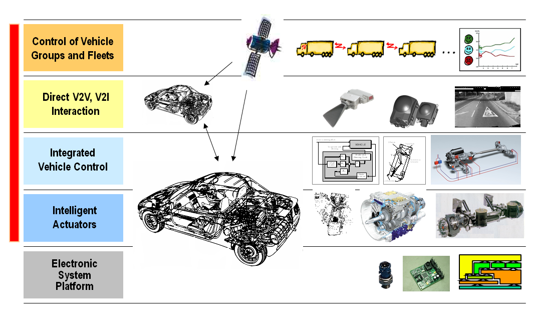
2.1.1. Electronic System Platform
The bottom level, the “Electronic System Platform“ solutions contain all the necessary building elements that are required for building up an electronically controlled vehicle system. This includes basic electronic and mechatronic hardware components like sensors and actuators, includes ECUs, but also software components like operating systems, diagnostics software, peripheral drivers and so on. The platform characteristics lies behind the fact that these individual components, building block can be used widespread in different makes and vehicle types, resulting in high production volume, thus reliable design and low costs.
2.1.2. Intelligent Actuators
The second level, the “Intelligent Actuators“ are the electronically controllable separate five main units of the vehicle drivetrain, namely the engine, transmission, suspension, brake system and the steering system. These main units are individual intelligences meaning that each unit has its own ECU with sophisticated functionality for electronic control in itself having communication links (CAN, FlexRay) to other ECUs for interaction, but one ECU is only responsible for the control of one unit. Typical characteristics of the intelligent actuators are having a dedicated interface for the electronic control of the whole unit. This is why they are often called as „by-wire“ systems, meaning that there is no mechanical connection for the control. In this case these units are referred as drive-by-wire, shift-by-wire, suspension-by-wire, brake-by-wire abs last but not least steer-by-wire systems in a vehicle. These actuators are “must have” components for the intelligent vehicle control.
2.1.3. Integrated Vehicle Control
In the next level, in the “Integrated Vehicle Control” there is a harmonized control of the intelligent actuators (instead of individual control) on a vehicle level. This layer has an influence on the whole vehicle motion. Maybe it is not trivial, but it is easy to understand what synergies become available in cases of harmonized or in other words integrated control of the intelligent actuators. The most obvious example is the integrated control of the brake and steering system, where the harmonized control could result in a significantly shorter brake distance. Let us imagine a so called u-split situation, where the road surface is divided into two parts based on a longitudinal separation. In this case the vehicles left hand side wheels (front left, rear left) are running on a hi-u surface e.g. u=0,8, while the right hand side wheels (front right, rear right) are running on a low-u surface e.g. u=0,1. In this case there is a great potential for synergy when the brake system realizes the u-split situation and instead of using “select-low” strategy – meaning that the lower u surface determines the maximum brake force on each sides – uses the maximum allowable braking force on each side with the help of the steering system providing compensating yaw torque to stabilize the vehicle direction.
2.1.4. Direct V2V, V2I Interactions
The fourth levels called “Direct V2V, V2I Interactions” where ad-hoc direct vehicle-to-vehicle (V2V) communications and ad-hoc direct vehicle-to-infrastructure (V2I) communications support the vehicle and its driver to be able to carry out the control task, safely and economically. The control is based on the relative position of the other vehicles or the elements of the infrastructure. The simplest example of these interactions is the Adaptive Cruise Control (ACC) function, where the distance and the velocity of the following vehicle is determined by a radar system, establishing ad-hoc direct V2V connection between the ego and the following vehicle. The ACC function is (currently) limited to the longitudinal direction, but such communication interactions can be established also in the lateral direction for e.g. automated trajectory planning. A currently market available example for ad-hoc direct V2I interaction is the automatic traffic sign recognition function.
2.1.5. Control of Vehicle Groups and Fleets
Last but not least there is the fifth level with “Control of Vehicle Groups and Fleets”. This layer covers the control of a whole vehicle flow or a partial set of the vehicles, where the grouping is based on either the current location or on the vehicle ownership (fleets).Good example for the location based selection of the vehicle groups is the control of a road cross section or the so called platooning, where an ad-hoc virtual road train is formulated on a highway. Transportation fleets are generally controlled via a centralized informatics system, where current market availability is rather logistics, delivery control and vehicle operation related information acquisition (FMS, Telematics) than remote movement control of the vehicles.
The above described structuring of the intelligent vehicle control is rather system oriented while the following part will mostly concentrate on the internal control structure of a vehicle.
2.2. Layers of vehicle control
For achieving an integrated control a possible solution could be to set the design problem for the whole vehicle and include all the performance demands in a single specification. Besides the complexity of the resulting problem, which cannot be handled by the existing design tools, the formulation of a suitable performance specification is the main obstacle for this direct global approach. In the framework of available design techniques formulation and successful solution of complex multi-objective control tasks are highly nontrivial.
From control design point-of-view the integrated vehicle control consists of five potentially distinct layers[16]:
-
The physical layout of local control based on hardware components, e.g. ABS/EBS, TCS, TRC, suspension.
-
Layout of simple control actions, e.g. yaw/roll stability, ride comfort, forward speed.
-
The connection layout of information flow from sensors, state estimators, performance outputs, condition monitoring and diagnostics.
-
The layout of control algorithms and methodologies with fault-tolerant synthesis, e.g. lane detection and tracking, avoiding obstacles
-
Layout of the integrated control design.
Research into integrated control basically focuses on the fifth layers; however the components of any integration belong to the third and fourth layer. The components in the first two layers are assumed to exist. Note, that to some extent the layers may be classified by the degree of centralization, e.g. centralized, supervisory or decentralized.
During the implementation of the designed control algorithms additional elements from information technology and communication will be included in the control process. In the classical control algorithms a lossless link is assumed to exist between the system and control these algorithms are concerned mostly with delays, parametrical uncertainties, measurement noise and disturbances.
The performance of the implemented control is heavily affected by the presence of the communication mechanism (third layer), the network sensors and actuators, distributed computational algorithms or hybrid controllers. It is useful to incorporate knowledge about the implementation environment during the controller design process, for example dynamic task management, adaptability to the state (faults) of sensors and actuators, the demands imposed by a fault tolerant control, the structural changes occurring in the controlled system.
From architectural design point of view the model based simulation of the planned architecture provides an early stage feedback about the potential bottlenecks in the design [21] [22]. Early stage simulation can reveal hidden mistakes that could turn out only after system implementation. When modification should be made on the implemented system due to the results of the safety analysis, it has much higher costs. The simulation based analysis needs lower costs, but takes time to prepare and carry out the simulations. The main advantage is that the simulation based analysis can be carried out from the early stage of the development. Certainly at the beginning of a system development, the system architecture is in its initial stage; therefore simulation model may also be inaccurate. The system design engineering and the safety engineering are parallel processes; the system model for the safety simulations is getting more and more accurate during the development. And there is a continuous feedback from the safety engineering to the system design engineering [23][24].
The software technology is not simply a software implementation of the control algorithm. The implementation and the software/hardware environment are also a dynamic system, which has an internal state and which respond to inputs and produces outputs. If the actual plant is combined with an embedded controller through the sensor and actuator dynamics, a distributed hybrid system is created. With this approach the control design is closely connected with software design. The control design is evolving through the development of hybrid optimal control, observability/controllability analysis, and software design is being facilitated by distributed computing and messaging services, real-time operating systems and distributed object models.
In the different prototype implementation of autonomous or highly automated vehicles a strictly defined layer structure can be observed that definitely corresponds to the above mentioned layer structure even if some layers are merged together for simplicity. The following figure shows the PEIT approach of the vehicle control layer structure[25]:
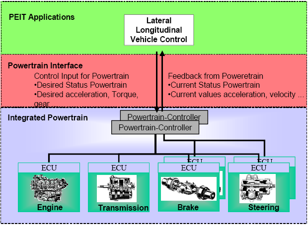
The PEIT architecture differentiates 3 different layers, namely the PEIT application layer, the powertrain interface and the integrated powertrain layer. The integrated powertrain layer contains 4 intelligent actuators, the drive-by-wire, the shift-by-wire, the brake-by-wire and the steer-by-wire systems. Important to notice that in the PEIT architecture the engine and transmission actuators are single subsystems, while the brake and steering systems are redundant subsystems. This is due to the requirement of availability based on the safety critical categorization of the subsystems. In case of the engine there is no backup function, in case of a transmission system there is only a “limp home” function which serves as a limited (e.g. one fixed gear) but useful functionality to maintain the movability of the vehicle. When it comes to the brake or the steering system it is obvious that any malfunction can result in serious consequences, so these systems must be designed in a way that they tolerate at least one failure. This is why safety critical systems have fault-tolerant architecture. There are different possible realizations of a fault tolerant system, one is simply using redundancy. In this case there are two parallel system elements that work simultaneously and in case of a failure one system can take over the control from the broken one. There is also a redundant powertrain controller can be found in the integrated powertrain layer, further dividing the layer into 2 sublayers. Referring back to the Prof. Palkovics the powertrain controller implements the vehicle level control, while the by-wire systems underneath are the intelligent actuators.
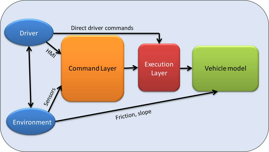
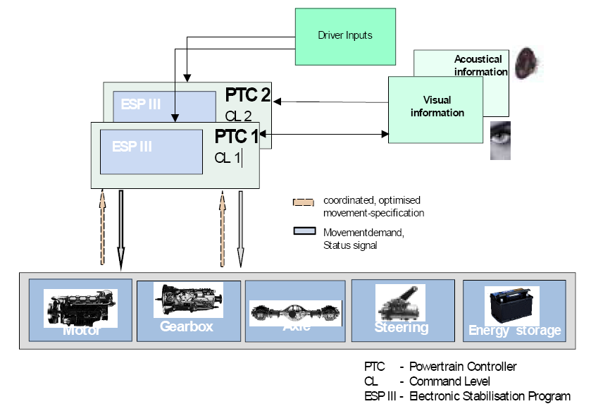
The HAVEit layer structure [6] is a further optimized, extended and structured architecture, where there are basically two main layers, namely the command layer and the execution layer. The interface in between is specifically called the “motion vector”. Even if there are a lot of other functions involved, the basic idea is that the command layer specifies the motion vector, which has to be followed by the vehicle that is carried out by the execution layer.
2.2.1. Command layer
The command layer contains the high level algorithms for the longitudinal and the lateral control of the automated vehicle. The command layer calculates the desired acceleration and direction and communicates the results to the powertrain via the powertrain interface, which also provides feedback about the vehicle state for the high level control.
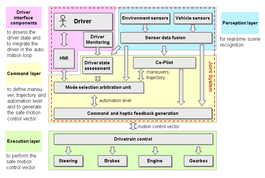
Based on the driver intention and the information coming from the perception layer the command layer defines the vehicle automation level and calculates the vehicle trajectory. The objective of the perception layer is to collect information about the external environment and the vehicle, thus providing information about vehicle status and objects in the surrounding environment. From this information the command layer determines the obtainable levels of vehicle automation and displays the options to the driver. Meanwhile the co-pilot calculates possible vehicle trajectories and prioritizes them based on the accident risk. The driver selects the desired level of vehicle automation from the available options via the HMI. Finally the mode selection unit decides the level of automation and selects the trajectory to be executed.
2.2.2. Motion Vector
The motion vector acts as an interface between the command layer and the execution layer. It is bidirectional, delivering longitudinal and lateral control commands to the powertrain and providing vehicle status feedback information for the higher level control.
This middle layer contains predefined data transfer for the control and the feedback of the powertrain. It includes commands for the vehicle control including the desired status of the powertrain and the required acceleration and torque. This interface also includes status feedback from the powertrain to the application layer providing important information whether the control action resulted in the required movement.
2.2.3. Execution Layer
The execution layer contains a full drivetrain control connected to intelligent actuators via a high speed communication network. As the implementation of a fully electronic interface (motion vector) for controlling the powertrain enables the replacement of the human driver for an electronic intelligence (auto-pilot), the execution layer cannot distinguish whether the commands are originated from a human driver or an auto-pilot. The commands are coming through the same interface, so the execution layer has to execute only. Considering that there are safety critical subsystems can be found among the intelligent actuators a fault-tolerant architecture is a prerequisite. This fault tolerant architecture not only includes duplicated powertrain controllers, steering and braking systems but also a redundant communication network, power supply and HMI to the driver. The following figure shows the powertrain control structure of the execution layer in the PEIT demonstrator vehicle[25].
2.3. Integrated control
Conventionally, the control systems of vehicle functions to be controlled are designed separately by the equipment manufacturers and component suppliers. One of the problems of independent design is that the performance demands, which are met by independent controllers, are often in interaction or even conflict with each other in terms of the full vehicle. As an example braking during a vehicle manoeuvre modifies the yaw and lateral dynamics, which requires steering action or, as another example, under/oversteering requires braking intervention. The second problem is that both hardware and software will become more complex due to the dramatically increased number of sensors and signal cables and these solutions can lead to unnecessary hardware redundancy.
The demand for the integrated vehicle control methodologies including the driver, vehicle and road arises at several research centres and automotive suppliers. The principle of integrated control with the CAN network was presented by Kiencke in [3]. The purpose of integrated vehicle control is to combine and supervise all controllable subsystems affecting vehicle dynamic responses. An integrated control system is designed in such a way that the effects of a control system on other vehicle functions are taken into consideration in the design process by selecting the various performance specifications. Recently, several important papers have been presented in this topic, see e.g. [4], [5], [6], [7], [8].
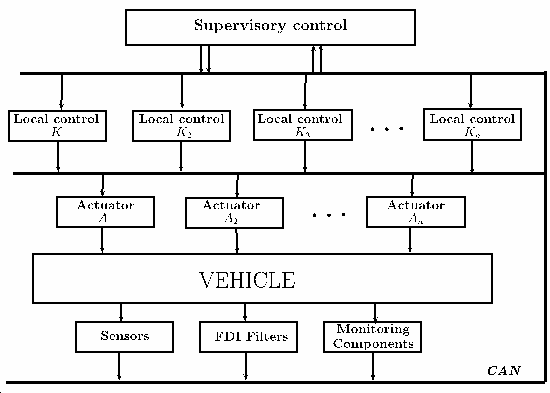
For achieving an integrated control a possible solution could be to set the design problem for the whole vehicle and include all the performance demands in a single specification. Besides the complexity of the resulting problem, which cannot be handled by the existing design tools, the formulation of a suitable performance specification is the main obstacle for this direct global approach. In the framework of available design techniques formulation and successful solution of complex multi-objective control tasks are highly nontrivial. Another solution to the integrated control is a decentralized control structure, in which there is a logical relationship between the individually-designed controllers. The communication between control components is performed by using the CAN bus (see Section 7.1). The advantage of this solution is that the components with their sensors and actuators can be designed by the suppliers independently. However, the local controllers require a group of sensors and hardware components, which may lead to different redundancies. The difficulty in the decentralized structure is that the control design leads to hybrid and switching methods with a large number of theoretical problems, see [8],[9],[10],11]. While stability of the control scheme assuming arbitrary switching can be ensured by imposing suitable dwell-times, it is hard to guarantee a prescribed performance level in general in the design process.
In more detail it means that
-
multiple-objective performance from available actuators must be improved,
-
sensors must be used in several control tasks,
-
the number of independent control systems must be reduced, at the same time the flexibility of the control systems must be improved by using plug-and-play extensibility.
These principles are close to the low-cost demands of the vehicle industry. In this way it should be possible to generate redundancy in a distributed way at the system level, which is cheaper and more effective than simply duplicating key components.
-
The integrated control consists of five potentially distinct levels:
-
The physical layout of local control based on hardware components, e.g. ABS/EBS, TCS, TRC, suspension.
-
Layout of simple control actions, e.g. yaw/roll stability, ride comfort, forward speed.
-
The connection layout of information flow from sensors, state estimators, performance outputs, condition monitoring and diagnostics.
-
The layout of control algorithms and methodologies with fault-tolerant synthesis, e.g. lane detection and tracking, avoiding obstacles
-
Layout of the integrated control design.
Research into integrated control basically focuses on the fifth layer, however the components of any integration belong to the third and fourth layers. The components in the first two layers are assumed to exist. Note, that to some extent the layers may be classified by the degree of centralization, e.g. centralized, supervisory or decentralized.
During the implementation of the designed control algorithms additional elements from information technology and communication will be included in the control process. In the classical control algorithms a lossless link is assumed to exist between the system and control these algorithms are concerned mostly with delays, parametrical uncertainties, measurement noise and disturbances.
The performance of the implemented control is heavily affected by the presence of the communication mechanism, the network sensors and actuators, distributed computational algorithms or hybrid controllers. It is useful to incorporate knowledge about the implementation environment during the controller design process, for example dynamic task management, adaptability to the state (faults) of sensors and actuators, the demands imposed by a fault tolerant control, the structural changes occurring in the controlled system.
The software technology is not simply a software implementation of the control algorithm. The implementation and the software/hardware environment are also a dynamic system, which has an internal state and which respond to inputs and produces outputs. If the actual plant is combined with an embedded controller through the sensor and actuator dynamics, a distributed hybrid system is created. With this approach the control design is closely connected with software design. The control design is evolving through the development of hybrid optimal control, observability/controllability analysis, and software design is being facilitated by distributed computing and messaging services, real-time operating systems and distributed object models.
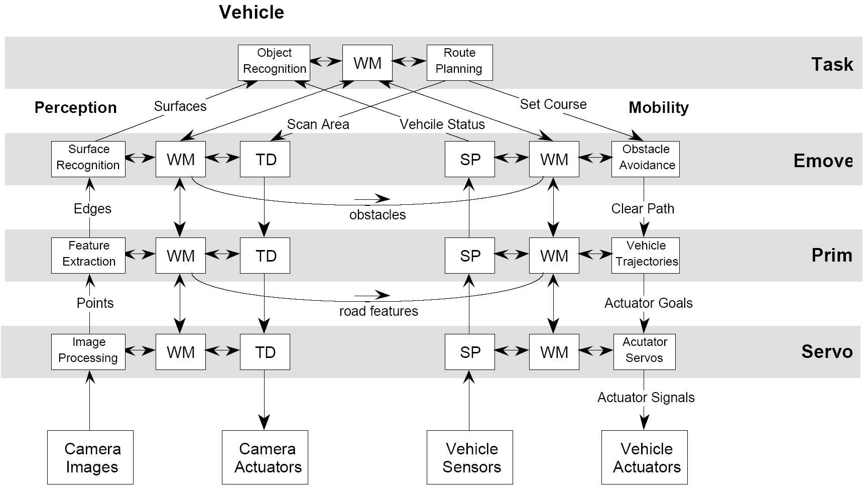
A reference control architecture for autonomous vehicles is presented in Figure 27. It shows how the software components should be identified and organized. This reference model is based on the general Real-time Control System (RCS) Reference Model Architecture, and has been applied to many kinds of applications, including autonomous vehicle control.
2.4. Distributed control structure
Another solution to the integrated control is a distributed (decentralized) control structure, in which there is a logical relationship between the individually-designed controllers. The communication between control components is performed by using the vehicle communication network (e.g. CAN bus). The advantage of this solution is that the components with their sensors and actuators can be designed by the suppliers independently. However, the local controllers require a group of sensors and hardware components, which may lead to different redundancies. The difficulty in the distributed structure is that the control design leads to hybrid and switching methods with a large number of theoretical problems, see [19][26][27][28]. While stability of the control scheme assuming arbitrary switching can be ensured by imposing suitable dwell-times, it is hard to guarantee a prescribed performance level in general in the design process.
Integrated control based on a distributed (decentralized) structure means that
-
multiple-objective performance from available actuators must be improved,
-
sensors must be used in several control tasks,
-
the number of independent control systems must be reduced, at the same time the flexibility of the control systems must be improved by using plug-and-play extensibility
These principles are close to the low-cost demands of the vehicle industry. In this way it should be possible to generate redundancy in a distributed way at the system level, which is cheaper and more effective than simply duplicating key components.