Chapter 9. Vehicle to Infrastructure interaction (V2I)
The Vehicle to Infrastructure interaction, similarly to V2V, is based on wireless communication technologies. The V2I communication (commonly called V2X) is also an extensively researched topic in the United States. The main traffic safety goals of such systems are well summarized by USDOT's (U.S. Department of Transportation) Connected Vehicles Program [117]. V2I is the wireless exchange of critical safety and operational data between vehicles and highway infrastructure, intended primarily to avoid or mitigate motor vehicle accidents but also to enable a wide range of other safety, mobility, and environmental benefits. V2I communications apply to all vehicle types and all roads, and transform infrastructure equipment into “smart infrastructure”. They incorporate algorithms that use data exchanged between vehicles and infrastructure elements to perform calculations that recognize high-risk situations in advance, resulting in driver alerts and warnings through specific actions. One particularly important advantage is the ability for traffic signal systems to communicate the signal phase and timing (SPAT) information to the vehicle in support of delivering active safety advisories and warnings to drivers.
9.1. Architecture
Several V2I architectures can be found in the different research papers. But generally these systems consist of the same key components, on the basis of which a general framework can be defined. Such an architecture framework was defined by USDOTs’ ITS Joint Program Office. The minimal V2I system should contain the following parts:
-
Vehicle On-Board Unit or Equipment (OBU or OBE)
-
Roadside Unit or Equipment (RSU or RSE)
-
Safe Communication Channel
The OBUs are the vehicle side of the V2I system. Practically the same physical device as for the V2V communication. In this document, references to the OBUs are used to describe the functions performed within the vehicle in addition to the radio transmission element. An OBU is logically composed of a radio transceiver (typically DSRC), a GPS system, an applications processor and interfaces to vehicle systems and the vehicle’s human machine interface (HMI). OBUs provide the communications both between the vehicles and the RSUs and between the vehicle and other nearby vehicles. The OBUs may regularly transmit status messages to other OBUs to support safety applications between vehicles. At intervals, the OBUs may also gather data to support public applications. The OBUs will accommodate storage of many snapshots of data, depending upon its memory and communications capacity. After some period of time, the oldest data is overwritten. The OBUs also assemble vehicle data together with GPS data as a series of snapshots for transmission to the RSU.
RSUs may be mounted at interchanges, intersections, and other locations (e.g. petrol stations) providing the interface to vehicles within their range. An RSU is composed of a radio transceiver (typically DSRC or WAVE), an application processor, and interface to the V2I communications network. It also has a GPS unit attached. Through an additional interface, it may support local infrastructure safety applications. The RSU is connected to the V2I communications network. Using its interface to the V2I communications network, it can send private data to and from the OEMs. The RSU may also manage the prioritization of messages to and from the vehicle. Although the OBU has priorities set within its applications, prioritization must also be set within the RSU to ensure that available bandwidth is not exceeded. Local and vehicle-to-vehicle safety applications have the highest priority; messages associated with various public and private network applications have lower priority. Entertainment messages will likely have the lowest priority.
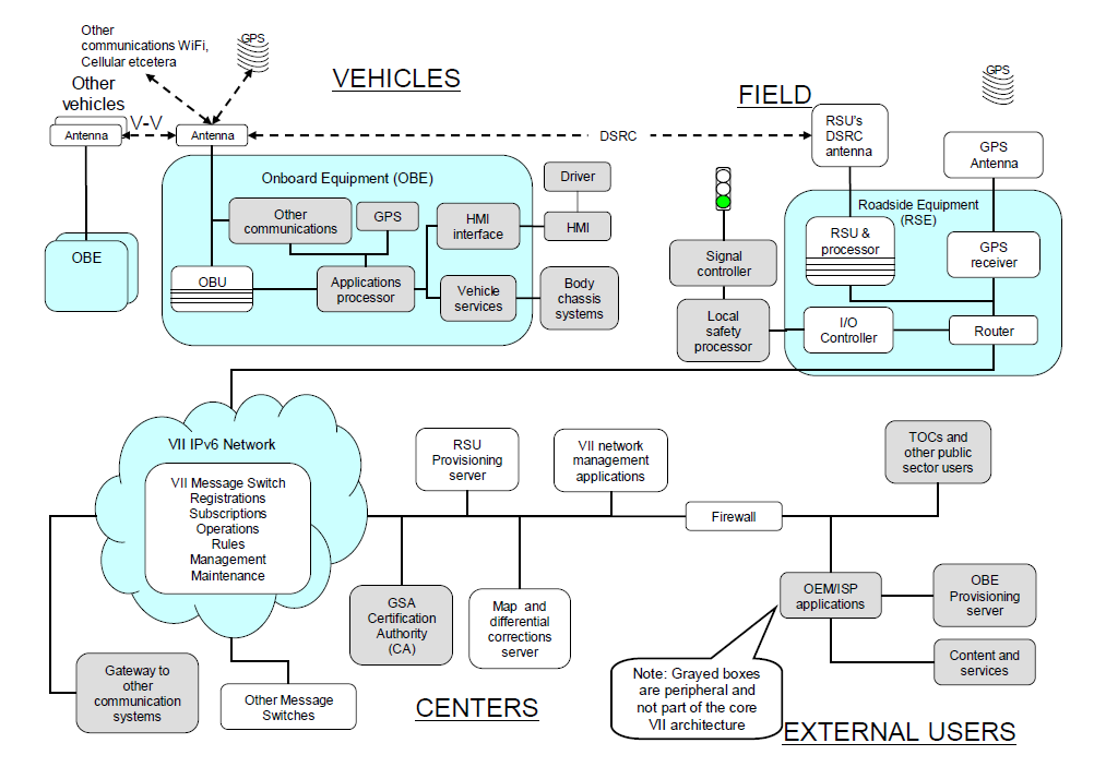
A typical V2I architecture can be seen in Figure 134 which was defined in Vehicle Infrastructure Integration program of USDOTs’ ITS Joint Program Office.
9.2. Wireless Technologies
9.2.1. DSRC
For V2I applications the same communication standards are used as in V2V systems. The standards mentioned in Section 8.2 take into consideration the infrastructure and its requirements. In the architecture definitions the concept of the RSU has been elaborated.
9.2.2. Bluetooth
Bluetooth technology is a wireless communications technology that is simple, secure, and can be found almost everywhere. You can find it in billions of devices ranging from mobile phones and computers to medical devices and home entertainment products. It is intended to replace the cables connecting devices, while maintaining high levels of security. Automotive applications of Bluetooth technology began with implementing the Hands Free Profile for mobile phones in cars. The development is coordinated by the Car Working Group (CWG) and is ongoing ever since 2000 by implementing different profiles and new features. The key features of Bluetooth technology are ubiquitousness, low power, and low cost. The Bluetooth Specification defines a uniform structure for a wide range of devices to connect and communicate with each other.
When two Bluetooth enabled devices connect to each other, is the so-called pairing. The structure and the global acceptance of Bluetooth technology means any Bluetooth enabled device, almost everywhere in the world, can connect to other Bluetooth enabled devices located in proximity to one another.
Connections between Bluetooth enabled electronic devices allow these devices to communicate wirelessly through short-range, creating ad hoc networks commonly known as piconets. Piconets are established dynamically and automatically as Bluetooth enabled devices enter and leave radio proximity meaning that you can easily connect whenever and wherever it's convenient for you. Each device in a piconet can also simultaneously communicate with up to seven other devices within that single piconet and each device can also belong to several piconets simultaneously. This means the ways in which you can connect your Bluetooth devices is almost limitless. There are applications that even do not require a connection establishment. It may be enough if the Bluetooth device’s wireless option is set to “visible” and “shown to all”, because fixed positioned Bluetooth access points may detect the movement of the Bluetooth device from one AP to another AP. This technology can easily be used for measuring the traffic flow.
A fundamental strength of Bluetooth wireless technology is the ability to simultaneously handle data and voice transmissions, which provides users with a variety of innovative solutions such as hands-free sets for voice calls, printing and fax capabilities, and synchronization for PCs and mobile phones, just to name a few.
The range of Bluetooth technology is application specific. The Core Specification mandates a minimum range of 10 meters or 30 feet, but there is no set limit and manufacturers can tune their implementations to provide the range needed to support the use cases for their solutions.
Range may vary depending on class of radio used in an implementation:
-
Class 3 radios – have a range of up to 1 meter or 3 feet
-
Class 2 radios – most commonly found in mobile devices – have a range of 10 meters or 33 feet
-
Class 1 radios – used primarily in industrial use cases – have a range of 100 meters or 300 feet
Bluetooth technology operates in the open and unlicensed industrial, scientific and medical (ISM) band at 2.4 to 2.485 GHz, using a spread spectrum, frequency hopping, full-duplex signal at a nominal rate of 1600 hops/sec. The 2.4 GHz ISM band is available and unlicensed in most countries. The most commonly used radio is Class 2 and uses 2.5 mW of power. Bluetooth technology is designed to have very low power consumption. This is reinforced in the specification by allowing radios to be powered down when inactive.
Bluetooth technology's adaptive frequency hopping (AFH) capability was designed to reduce interference between wireless technologies (such as WLAN) sharing the 2.4 GHz spectrum. AFH works within the spectrum to take advantage of the available frequency. This is done by the technology detecting other devices in the spectrum and avoiding the frequencies they are using. This adaptive hopping among 79 frequencies at 1 MHz intervals gives a high degree of interference immunity and also allows for more efficient transmission within the spectrum. For users of Bluetooth technology this hopping provides greater performance even when other technologies are being used along with Bluetooth technology. The AFH technology is shown in Figure 135 [118].
The newest Bluetooth Technology is Bluetooth 4.0 called Bluetooth Smart (Low Energy) Technology. While the power-efficiency of Bluetooth Smart makes it perfect for devices needing to run off a tiny battery for long periods, the most important attribute of Bluetooth Smart is its ability to work with an application on the smartphone or tablet you already own. Bluetooth Smart wireless technology features:
-
Ultra-low peak, average and idle mode power consumption
-
Ability to run for years on standard coin-cell batteries
-
Low cost
-
Multi-vendor interoperability
-
Enhanced range
In automotive industry the primary usage of Bluetooth connects hands-free car systems which help drivers focus on the road. Another special usage is health monitoring e.g. people with diabetes can monitor their blood-glucose levels by using a Bluetooth glucose-monitoring device paired with the car. Also in-vehicle intelligent interfaces may provide e.g. vehicle related technical information to the driver via a Bluetooth channel. (Source: [119])
In V2I systems Bluetooth can be used to provide communication channel between the car and the traffic signal systems. Nowadays several manufacturers offer Bluetooth capable traffic control devices. It is capable for privileging the public transport at the intersections or measuring the traffic and pedestrian flows with the help of the electronic devices installed with Bluetooth radio (such as smartphones, tablets, navigation units etc.). These systems detect anonymous Bluetooth signals transmitted by visible Bluetooth devices located inside vehicles and carried by pedestrians. This data is then used to calculate traffic journey times and movements. It reads the unique MAC address of Bluetooth devices that are passing the system. By matching the MAC addresses of Bluetooth devices at two different locations, not only the accurate journey time is measured, privacy concerns typically associated with probe systems are minimized.
9.2.3. WiFi
WiFi (Wireless Fidelity) or WLAN (Wireless Local Network) communication system is based on the Institute of Electrical and Electronics Engineers' (IEEE) 802.11 standards. The 802.11 family consists of a series of half-duplex over-the-air modulation techniques that use the same basic protocol. The most popular are those defined by the 802.11b and 802.11g protocols, which are amendments to the original standard. 802.11-1997 was the first wireless networking standard in the family, but 802.11b was the first widely accepted one, followed by 802.11a, 802.11g and a multi-streaming modulation 802.11n. Other standards in the family (c–f, h, j) are service amendments and extensions or corrections to the previous specifications. The IEEE 802.11p WAVE is intended to amend the overall IEEE 802.11 standard as mentioned in Section IEEE 802.11p (WAVE) 8.2.1.
802.11b and 802.11g use the 2.4 GHz ISM band. Because of this choice of frequency band, 802.11b and equipment may occasionally suffer interference from microwave ovens, cordless telephones and Bluetooth devices. 802.11b and 802.11g control their interference and susceptibility to interference by using direct-sequence spread spectrum (DSSS) and orthogonal frequency-division multiplexing (OFDM) signalling methods, respectively.
The “general” IEEE 802.11 standards (that used in consumer electronics) can support only infotainment applications in the vehicle. Only the IEEE 802.11p WAVE (DSRC) is capable for safe and reliable communications in V2X applications.
9.2.4. Mobile networks
The most wide-spread mobile (cellular) network technology is GSM (Global System for Mobile communication). GSM was designed principally for voice telephony, but a range of bearer services was defined (a subset of those available for fixed line Integrated Services Digital Networks, ISDN), allowing circuit-switched data connections at up to 9600 bits/s. The technology behind the Global System for Mobile communication (GSMTM) uses Gaussian Minimum Shift Keying (GMSK) modulation, a variant of Phase Shift Keying (PSK) with Time Division Multiple Access (TDMA) signalling over Frequency Division Duplex (FDD) carriers. Although originally designed for operation in the 900 MHz band, it was soon adapted also for 1800 MHz. The introduction of GSM into North America meant further adaptation to the 800 and 1900 MHz bands. Over the years, the versatility of GSM has resulted in the specifications being adapted to many more frequency bands to meet niche markets.
At the time of the original system design, this rate compared favourably to those available over fixed connections. However, with the passage of time, fixed connection data rates increased dramatically. The GSM channel structure and modulation technique did not permit faster rates, and thus the High Speed Circuit-Switched Data (HSCSD) service was introduced in the GSM Phase 2+.
During the next few years, the General Packet Radio Service (GPRS) was developed to allow aggregation of several carriers for higher speed, packet-switched applications such as always-on internet access. The first commercial GPRS offerings were introduced in the early 2000s. Meanwhile, investigations had been continuing with a view to increasing the intrinsic bit rate of the GSM technology via novel modulation techniques. This resulted in Enhanced Data-rates for Global Evolution (EDGE), which offers an almost three-fold data rate increase in the same bandwidth. The combination of GPRS and EDGE brings system capabilities into the range covered by the International Telecommunication Unions IMT-2000 (third generation) concept, and some manufacturers and network operators consider the EDGE networks to offer third generation services.
In 1998, the ETSI (European Telecommunications Standards Institute) General Assembly took the decision on the radio access technology for the third generation cellular technology: wideband code-division multiple access, W-CDMA, would be employed. A dramatic innovation was attempted: a partnership project was formed with other interested regional standards bodies, allowing a common system to be developed for Europe, Asia and North America. The Third Generation Partnership Project (3GPP) was born. (Source: [120])
The Third Generation mobile cellular technology developed by 3GPP - known variously as Universal Mobile Telecommunications System (UMTS), Freedom of Mobile Multimedia Access (FOMA), 3GSM, etc., is based on wideband code division multiple access (W-CDMA) radio technology offering greater spectral efficiency and higher bandwidth than GSM. UMTS was originally specified for operation in several bands in the 2 GHz range. Subsequently, UMTS has been extended to operate in a number of other bands, including those originally reserved for Second Generation (2G) services. The UMTS radio technology is direct-sequence CDMA, each 10 ms radio frame is divided into 15 slots.
As a development of the original radio scheme, a high-speed download packet access (HSDPA, offering download speeds potentially in excess of 10 Mbit/s), and an uplink equivalent (HSUPA, also sometimes referred to as EDCH) were developed. Collectively the pair are tagged HSPA, and permit the reception of multimedia broadcast/multicast, interactive gaming and business applications, and large file download challenging traditional terrestrial or satellite digital broadcast services and fixed-line broadband internet access. The radio frames are divided into 2 ms subframes of 3 slots, and gross channel transmission rates are around 14 Mbit/s.
3GPP's radio access undergoes continuous development and the 'long-term evolution' (LTE) exercise aims to extend the radio technology to keep UMTS highly competitive to potential rival technologies, with data rates approaching 100 Mbit/s by the end of the decade. (Source: [121])
9.2.5. Short range radio
Short range radio means an older technology, which is wide-spread in case of public transport vehicles. They have been installed with a short range radio transmitter which works on a lower ISM band (such as 433 or 868 MHz). It can broadcast an identifier which can be received by the traffic control systems’ roadside beacon and thus the public transport vehicles can be prioritized in the intersections or by the stops.
9.3. Applications
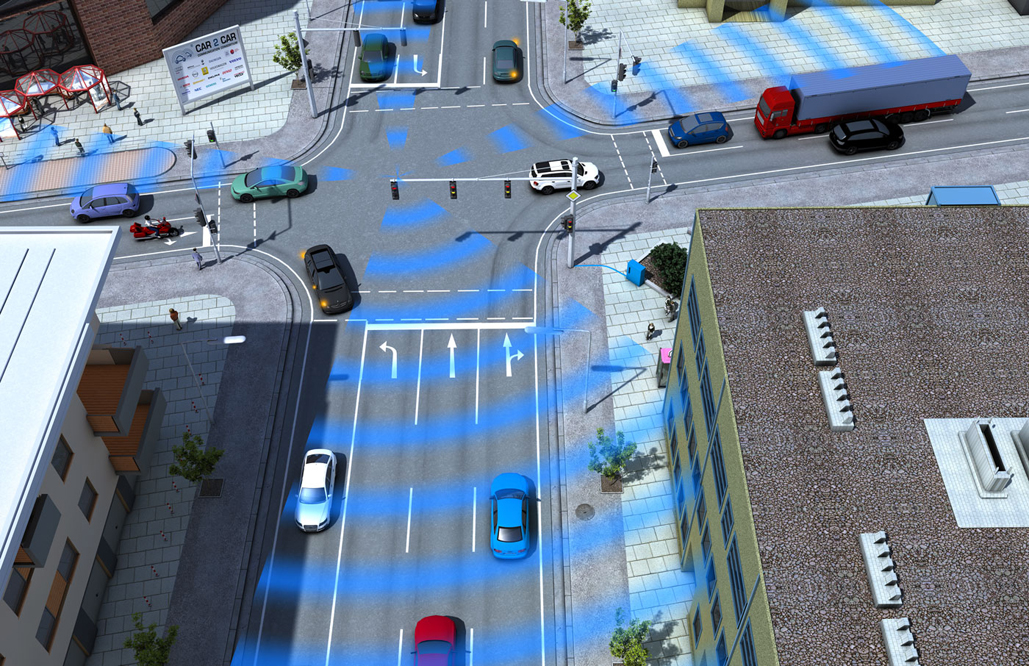
As mentioned above the V2I systems are closely related to the V2V communications. Most of the V2I applications rely on the V2V on-board units, so these applications can commonly called Intelligent Transportation System (ITS) applications. Naturally several applications currently exist which based only on roadside sensors, typically which require only observation (e.g. toll control, speed measurement etc.).
9.3.1. Safety
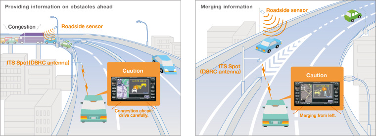
The safety applications aim to decrease the number of accident by prediction and notifying the drivers of the information obtained through the communications between the vehicles and sensors installed on the road.
The typical safety applications could be the following:
-
warning for hazardous situations (such as congestions, accidents, obstacles etc.),
-
merging assistance,
-
intersection safety,
-
speed management,
-
rail crossing operations,
-
priority assignment for emergency vehicles.
9.3.2. Efficiency
The efficiency applications can support the better utilization of the roads and intersections. These functions can operate locally at an intersections or a given road section, or in an optimal case on a large network, such as a busy downtown. It is important to note that the efficiency applications also have a beneficial effect on safety in most cases.
The following typical applications can enhance the traffic efficiency:
-
traffic jam notification,
-
prior recognition of potential traffic jams,
-
dynamic traffic light control,
-
dynamic traffic control,
-
connected navigation
9.3.3. Payment and information
The number plate recognition serves as base for the payment applications, which is well-tried and reliable camera-based technology. The payment applications could be the following:
-
parking control,
-
congestion charge,
-
highway toll control.
The information services can be typically the conventional variable traffic signs or temporary road signs supplemented with a DSRC beacon.