Chapter 14. Fleet Management Systems
The Fleet Management System collects, store and provide complete comprehensive information about the current state of the vehicles and cargo, the route history, the expected events, as well as the driver activities for the vehicle maintenance and operator companies.
The main fields of application are the following:
vehicle operation,
traffic safety,
security of freight,
traffic management,
environmental protection.
14.1. Motivation
Thanks to the rapid development of microelectronics and mobile telecommunications by the end of the 90’s a wider range of fleet diagnostics and satellite tracking became possible. These innovations gave a technological background of the creation of fleet management systems. Economical demand for Fleet Management Systems strengthened as an effect of the increased competitive situation in passenger and freight transport especially in road traffic. This effect was strengthened by the growth of traffic density and the intensification of transportation demand in Europe. One of the social impacts of this progression is an increase in the number of accidents that intensifies the demand for safer vehicles.
Spread in on-line Fleet Management Systems was greatly aided by the constant decrease of communication charges and the increase of speed in mobile data transmission.
For all these reasons in the 2000s on-line Fleet Management Systems spread rapidly.
Its’ advantages are the following:
a greater safety in delivery,
aiding dynamic freight arrangement,
constant tracking of the mechanical condition of the vehicles,
reduction of operational costs (fuel consumption and maintenance costs),
avoidance of the illegal usage of the vehicle and the fuel manipulation,
easier documentation (e.g. journey log),
driver motivating system (driving style analysis),
developing safety of traffic (speeding and accident detection),
developing security of freight,
increased environmental protection.
In the following sections the structure, the elements, the functions, and the operation of the Fleet Management System will be introduced, with a special regard on on-line systems.
14.2. General requirements in transportation
14.2.1. Cost reduction
The main reason of the installation of a Fleet Management System is the expected decrease in the overall operating costs of the company. Though the establishment of such a system requires one-time costs of investment and its operation also imply costs, but these expenses are counterbalanced by the savings. The cost reductions arising from the more effective operation are typically the followings:
Reduction of operation costs thanks to the increase in vehicle utilization and optimal route planning.
The Fleet Management System provides the possibility of the maximal utilization of the vehicle parts’ lifetime by the complex monitoring of the vehicle. Simultaneously it warns for the necessity of the replacement and supports the logistics solutions also.
The system may improve the quality of the estimation of the fuel norm through the measurement of the real consumption.
14.2.2. Logistics management
The possibility of on-line vehicle tracking is an ideal tool for the optimization of the logistic processes. Not only the route of the goods can be determined, but the vehicle movements can be optimized. The improvement in logistics costs could be the followings:
Improve efficiency of freight transport
Decrease of extra charges caused by the delays.
Significant decrease in vehicle stop time can be reachable resulting in cost reduction with keeping the same transportation performance.
Monitoring helps forcing back the illegal utilization of the company’s vehicle.
Another requirement is to provide the safety of the freight through using Fleet Management System. The data acquired make possible to follow or retrace the vehicle events. With using on-line system it is possible to intervene in critical situations and to monitor the keeping the traffic regulations.
The following section presents the kind of functionality and the system architecture that can satisfy the above mentioned requirements.
14.2.3. Vehicle categories
Initially the Fleet Management Systems were introduced by the international transport companies with heavy commercial vehicles (large goods vehicle). These early systems have collected only the GPS positions and sent it by SMS to the central server. With the reduction of costs the FMS solutions have broken into the segment of the smaller commercial vehicles (light commercial vehicles). Nowadays the FMS is used almost in all vehicle segments, typically in the following ones:
large goods vehicle (commercial vehicles over 3.5 tons)
light commercial vehicles (commercial vehicles not more than 3.5 tons)
passenger vehicles
construction and agricultural machinery
14.3. System Functions
Early FMS systems, Initially the FMS systems were only capable of identifying GPS position and sending it in an SMS to the central server. Over the past decade the Fleet Management Systems have gone through a tremendous development. Nowadays these systems use several sensor sources, on-line packet switched data connection, bidirectional communication, feedback, on-board vehicle communication buses, improved MMI and driver identification, digital tachograph data etc. In the following subsections the system function groups will be detailed.
14.3.1. Data acquisition
Data acquisition and data handling give the basis of Fleet Management Systems. Primarily the on-board system should register existing vehicle signals, still in several cases the system needs new or more detailed parameters. Several possibilities are available for measuring the physical parameters and acquiring identification data (driver, trailer etc.). Nowadays all commercial vehicles possess multiple CAN interfaces providing various signals.
14.3.2. Data processing
Data processing includes the sampling of various sensor sources either dynamically or fixed time based. Sampling strategy determines the overall amount of data to be handled, that may require temporary storage and pre-processing (e.g. histogram generation) to lower communication costs.
14.3.3. Data transmission
There are two categories of Fleet Management Systems, depending on the data location. If there is a recording unit in the vehicle and the recorded data are processed and evaluated afterwards, it is called off-line Fleet Management System. When all the vehicles are connected on-line to a computer server over mobile internet, and real-time information and data evaluation is available, is called the on-line Fleet Management System. In the recent years the on-line systems have come into general use as the result of the evolution of the wireless communication technologies. Several communication possibilities have become reachable for fleet management systems. The generally used techniques are based on GSM networks mainly on packet-switched services (like GPRS). In the future UMTS technologies will expand the possibilities and data bandwidth will be no longer a bottleneck for any function.
14.3.4. Identification tasks
The identification of the motor vehicle is an essential task in Fleet Management Systems. This function can be achieved in several ways. The general solution is to use the “natural” identifier of the GSM unit called IMEI number which can be connected to the vehicle’s license plate or the vehicle identity number (VIN) in the central server’s relational database.
Identification increases system safety by connecting the vehicle data to the driver. Driver identification is very important from several aspects: work time registration, responsibility issues in case of special events etc. Nowadays a lot of different solutions can be reached on the market such as proximity (RFID) cards, Dallas keys, but recently the smart card based digital tachographs opened new possibilities on this field.
Another highly important task is trailer identification which is necessary for cargo tracking. It can be realized via the spiral cable between the tractor and the trailer or with a wireless identification system.
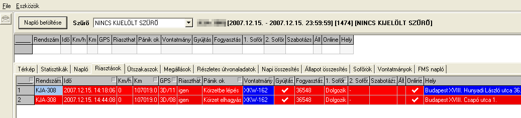
14.3.5. Alerts
Event-triggered alerts enable the system to indicate abnormal operations to the driver and to the system centre also. These functions generally monitor specified signals. In case these signals reach unexpected or dangerous value an event will occur. For example these events can be the sudden decrease of the fuel level, speeding, tyre pressure etc.
Specific characteristic of the alerts is that they are real-time to enable quick intervention.
14.3.6. Positioning
Determining the vehicle’s location is usually performed by GNSS systems (see Section 3.8). The principles of the satellite-based navigation systems (called GPS) were developed in the United Sates for military navigation purposes. The GPS is a widespread and reachable positioning solution which is capable of determining 3D position, chronometry and measurement of velocity. The system uses satellite signals for the determination of the position, thus it ensures continuous measurement possibility in 0-24 hours on the whole World. The Fleet Management Systems usually use GPS receivers or combined GPS/GLONASS receivers.
14.3.7. Central system (Back office)
The central system of the fleet management systems is a complex hardware and software system, which handles data acquisition, storage and evaluation tasks. The incoming data from the vehicles must be handled in safe and reliable way for avoiding data loss and unauthorized access. The central system generates reports, charts, alerts and handles the geographic tasks.
14.3.8. User system (Front office)
Since the front office is the interface to the staff operating the system, it has to provide the following functionalities: primarily the system operator should gather vehicle, route and driver data through customizable reports. In addition for the tasks of on-line fleet control it has to possess geographical algorithms, and visualization. Since data security is highly important in such systems, the authentication and authorization in the whole system including the back office and also the front office must be managed and designed carefully.
14.4. Architecture of Fleet Management Systems
General construction of on-line fleet management systems are demonstrated on Figure 152. Usually it consists of three main sub-systems, see [137]:
on-board units,
central server,
user computers.
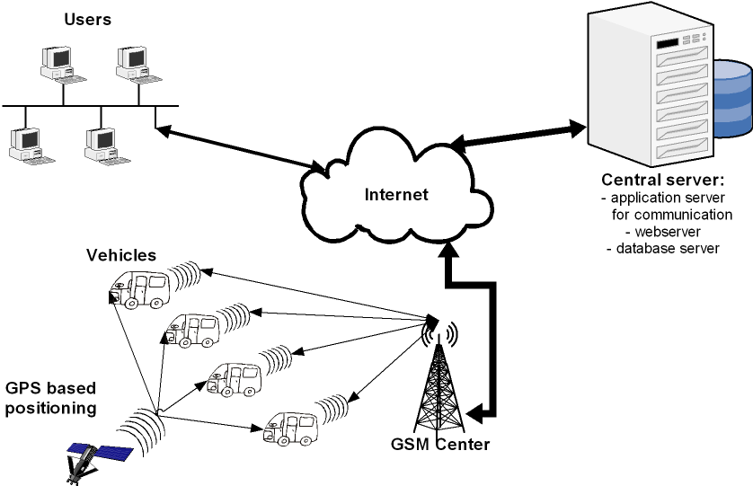
The operation of the system is the following. The on-board units (OBU) measure the operational parameters of the vehicle (state of the switches, energy consumption, motor parameters, etc.), and its position (aided by GPS-based location), and they store the data given by the driver (the name of the actual activity, etc.). These parameters are sent to a central server at the actualization of previously defined events (alarm-signal, sudden decrease in fuel level, etc.) and in previously defined periods of time.
On-board units communicate with the central server through mobile systems. The incoming data are evaluated and stored in a relational database. If necessary the central server can send an alarm to a given e-mail address or even a mobile phone. In this structure the communication from the server towards the vehicle is plausible as well. Aided by this the incoming data packages can be confirmed, a text message can be sent to the driver and the parameters of the on-board unit can be set.
Vehicles are detectable and observable almost constantly (on-line) and the operating parameters (running performance of vehicles, energy consumption, activities and work time of drivers, delivery performance) can be followed by a later evaluation of data stored in the centre (off-line).
14.4.1. On-board units (OBU)
In the building of the on-board unit (Figure 153) the important aspects are a heavy-duty design (EMC protection, shake protection, fluctuation of environmental temperature, etc.) and modularity. Therefore one should use a system that is built up of individual units. The connection of these by a series communication connection is worth realizing for the sake of simplicity and easy expansion.
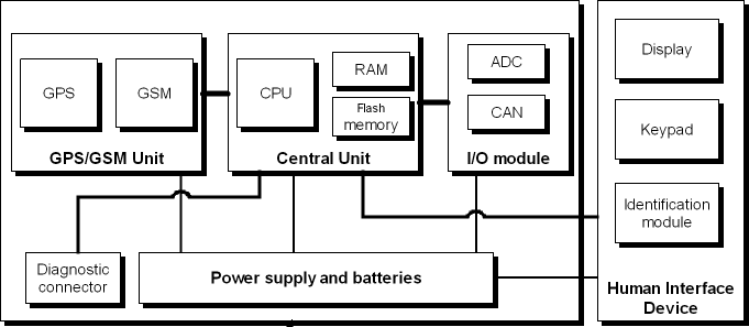
The on-board unit is made up of the following main units:
GSM/GPS module,
central unit,
human interface device,
diagnostic adapter,
I/O module,
power supply unit and background batteries.
The basic on-board units are often referred to as AVL. The abbreviation of AVL stands for Automatic Vehicle Locator[138], most commonly called as vehicle tracking device. There are GPS and/or GLONASS based positioning systems integrated together with an industrial GSM/UMTS modem, which sends the positioning information on-line to a central computer server. AVL devices may be extended with vehicle technical information like fuel tank level, engine revolution, fuel used, and so on.
14.4.1.1. In-Vehicle Data Acquisition
The most important and most complex function of the on-board unit is the exact acquisition of the vehicle data with special regard to the fuel consumption.
There are two ways to collect the necessary data:
sensor retrofit
in-vehicle communication buses
Formerly the first alternative was used generally because of the low penetration and hard reachability of the in-vehicle communication buses. This solution has several drawbacks, such as high cost, low reliability and accuracy, safety and warranty problems etc.
The other solution is generally based on the CAN bus technology, see [139]. CAN stands for Controller Area Network, meaning a computer network formulated by the vehicle’s electronic control units (ECU). CAN was primarily developed for automotive applications but later - due to its simplicity, reliability and electromagnetic immunity - it appeared also in industrial (CANopen), military (MilCAN), aerospace (CANaerospace) and nautical (SeaCAN) applications.
CAN bus is an asynchronous (time-shifted) serial bus system, originally developed by Robert Bosch GmbH from 1983 to interconnect electronic control units (ECU) in motor vehicles and was introduced in different steps to reduce cable harnesses and thereby weight. Instead of using an electrical circuit for each transmitted signal, the "bus" is based on a communication platform that regulates the relaying of messages between several devices.
In a practical context, the process is as follows: While the rear light was actuated by means of guiding a current to the rear light, the bus system only relays a message: "Light switch to rear light: Switch on!" Translating all control signals into messages requires a "greater intelligence" of the connected devices, at the same time this implies that many devices can exchange information, virtually at same time, using a very limited number of cable connections. (Source: [140])
All the necessary vehicle data is reachable on one of the vehicle CAN buses. There are great numbers of vehicle manufacturers having different types of vehicles on the market. They all have specific in-vehicle communication systems. To be able to “understand” each vehicle, one has to learn all these specific “languages”. Practically that means the developers of the Fleet Management Systems cannot interpret the data on the vehicle’s CAN bus. It is caused by the lack of the standardization of the CAN messages or the slight of the standards by the vehicle manufacturers.
In 2002, six major truck manufacturers (Volvo, Scania, Iveco, MAN, DAF, Mercedes-Benz) decided to create a standardized vehicle interface for these GPS based tracking systems, called the Fleet Management System Standard (FMS Standard). Since the establishment of the FMS Standard, there is no need to learn just one “language”. No matter which OEM produced a vehicle, if it was equipped with an FMS interface (FMS Gateway), there is the same output for all vehicles. The standard itself was a huge step forward in fleet management, since telematics devices (AVL) could access vehicle technical information without the need of vehicle specific developments.
FMS Standard versions:
FMS Standard 1.0 (Initial standard issued in 2002)
Bus FMS standard (Ver. 00.01 issued in 2007, specialized standard for buses and coaches including specific signals like door openings, etc. Since then the original “FMS Standard 1.0” was also referred as “Truck FMS Standard”)
FMS Standard 2.0 (extended standard issued in 2010. This standard took over some signals from the Bus FMS Standard, but FMS Standard 2.0 was still handled separately for Trucks.)
FMS Standard 3.0 harmonized Bus and Truck standard (issued in 2012). From now on there is only FMS Standard 3.0, but there are separated sections inside for buses and trucks.
The development of FMS-standard is now under the umbrella of the European Automobile Manufacturers’ Association (ACEA). The dedicated working group “Heavy Truck Electronic Interface Group” meets regularly to discuss the needs of the FMS-standard. (Source: [141])
Now third-party solutions can be reached on the market for CAN-based data acquisition for vehicles without FMS interface. For example Inventure FMS Gateway which is an intelligent and cost-effective CAN bus interface with aim to monitor fuel consumption and other vehicle parameters. It helps to prevent fuel theft, avoid unnecessary operational expenses and protect the environment while driving smarter. Inventure FMS Gateway connects to the vehicle communication network, collects, processes using high precision algorithms and transfers vehicle related technical information to GPS based fleet management (AVL) systems. Inventure FMS Gateway can replace expensive and time consuming manufacturer’s FMS interface installation and activation. It represents general solution for all types of vehicles. It supports multiple output protocols such as CAN (FMS Standard compatible), serial (RS232) and Bluetooth. (Source:[142])
14.4.2. Communication
By the on-line fleet management systems the data have to be transferred with high reliability and integrity.
At present the fleet management systems use the public GSM network for data transmission. There are three possible technologies for this task:
SMS based,
circuit-switched and
packet-switched.
Nowadays the packet-switched communication is used most frequently. The most widespread is the GPRS (General Packet Radio Service), and EGPRS (Enhanced GPRS) which ensures larger bandwidth. In the 3G networks the UMTS and HSDPA can be used, but these techniques haven’t come into general use in fleet management systems because of the low covering and high prices of the devices.
The advantages of the packet switched technologies are the following:
continuous connection,
larger bandwidth,
data amount based costs,
low prices.
The SMS based data transmission can be a backup in case of GPRS service’s unavailability and it can be used for special purposes, for example sending alerts directly to mobile phones.
An example communication system can be built up by OSI model [143] as shown on Table 4.
|
OSI model |
Used protocol or service |
|
Physical layer |
GSM, 100BASE-TX |
|
Data link layer |
GPRS, Ethernet |
|
Network layer |
Internet Protocol (IP) |
|
Transport layer |
Transmission Control Protocol (TCP) |
|
Session layer |
TCP socket |
|
Presentation layer |
UTF8 |
|
Application layer |
XML based protocol |
There are several other possibilities elaborating the communication system. The first 3 layers are given when using GPRS networks. In the transport and session layers the UDP (User Datagram Protocol) or TCP (Transmission Control Protocol) can be used. UDP uses a simple, connectionless transmission model with a minimal protocol mechanism[144]. It has no handshaking process, thus any unreliability of the underlying network protocol devolves to the user's program. There is no guarantee of delivery, ordering, or duplicate protection. UDP provides checksums for data integrity, and port numbers for addressing different functions at the source and destination of the datagram. The TCP provides reliable transport layer above the IP, and also a session layer (TCP socket). The key features that set TCP [145] apart from User Datagram Protocol:
three-way handshake
Ordered data transfer,
Retransmission of lost packets,
Discarding duplicate packets,
Error-free data transfer,
Congestion/Flow control.
The presentation and application layers can be divided into two main groups:
simple byte-stream with a special packet structure,
markup language (e.g. XML) or other human-readable text format (e.g. JSON).
The first alternative is a modern, easy to handle solution which is primarily used in web-based communication systems. The advantages are the human-readability, the easy expandability and the off-the-shelf development tools. The main disadvantages are the verbosity and the unnecessary redundancy.
The byte-stream based protocols are widespread in Fleet Management Systems, because of the low-computing requirement and low amount of data. Nowadays the functions of the Fleet Management Systems are continuously expanding, thus the byte-stream based protocols become more difficult to handle by the developers and to integrate them into the modern web-based solutions.
14.4.3. Central system
The central system (Figure 154) based on a server system which consists of several databases and application servers. The on-board units connect to a communication server which implements the protocol. It has to deal with the following tasks:
data receiving,
data checks (syntactic, semantic, checksum),
data conversion and passing to the database,
acknowledging to the clients,
identification of the drivers,
sending the parameters of the OBU,
software update.
The communication server connects to a database system which contains three main databases:
transactional database,
data warehouse,
map database.
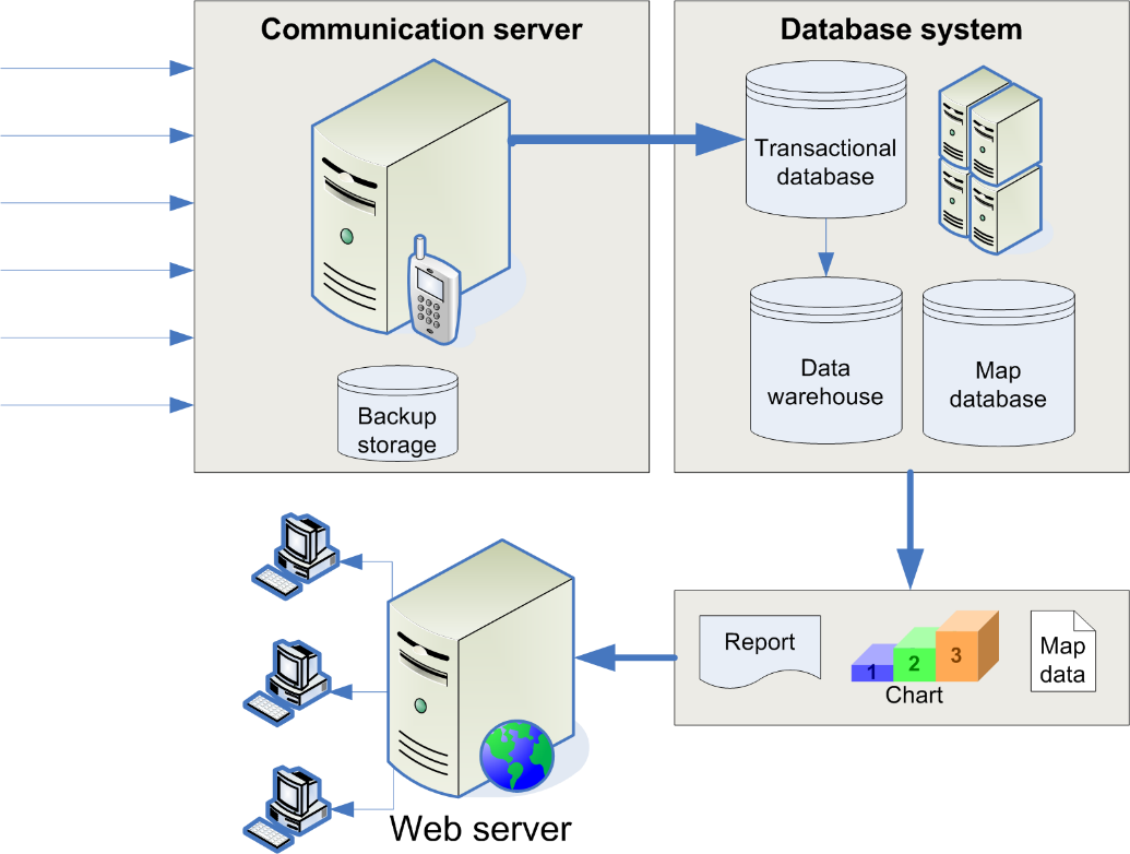
The task of the transactional database is receiving the data from the communication server with high speed and reliability. The data is transferred to a data warehouse which executes several filtering and pre-processing procedures.
The users can access reports, charts and map data on a web-based user interface.
14.4.4. User System
The user system consists of the user computers which are connected to the server system and the user software. It can be stand-alone software with a network database connection or web-application. Nowadays the web-based solutions are dominant (and can be called modern) because of the significant advantages (such as the easier software update and the minimal requirements on the client-side). It is important to note that in the recent years the web-based technologies are developing rapidly, thus made it possible to implement all of the necessary functions and ergonomic graphical interfaces for the effective work. A Fleet Management System can include many user functions [138]:
Vehicle maintenance
Vehicle tracking and diagnostic
Fuel management
Driver management
Tachograph management (Remote download)
Health and safety management
Basically the user system should display the geographical data of the vehicles on a map and the base vehicle data with easy filtering and ordering possibilities.
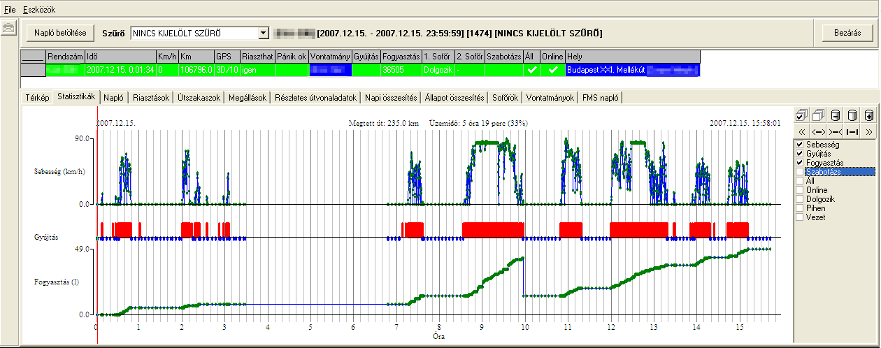
14.4.4.1. Data displaying, querying, reporting
Large amount of data in itself does not answer the questions of the fleet owner. Suitable business intelligence (BI) solutions are necessary for the data analysis, see [146]. Reporting and displaying system should be designed to support differently the employees with diverse roles considering the executive levels of the company. During the system design phase it is hard to determine all of the necessary and suitable reports. Thus it is important to give the opportunity of the flexible querying for future application.
The system should provide the following output formats:
diagram,
histogram,
statistics,
report.
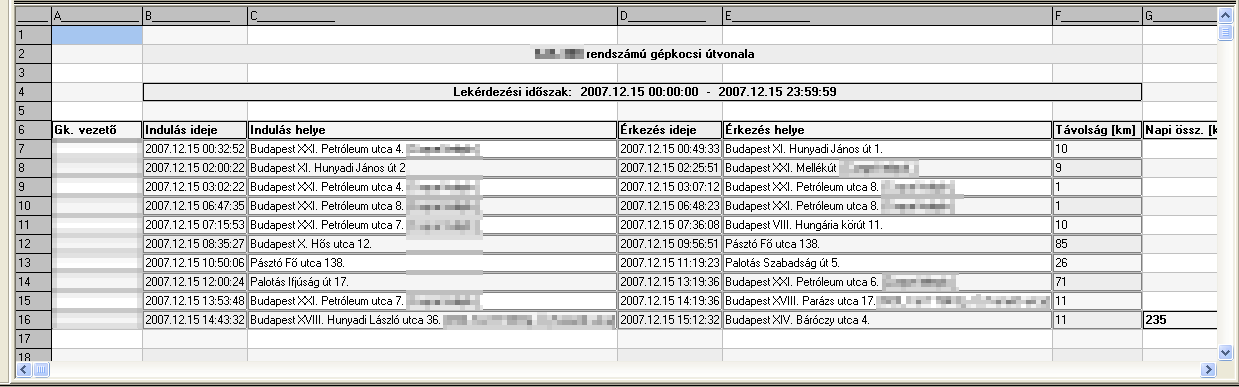
As a result of the data analysis several outputs can be generated in the above mentioned formats. The generally used outputs are the following:
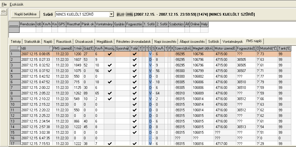
journey log,
vehicle parameter reports and histograms.
driver style classification,
fuel consumption,
event log,
alarm log,
These outputs can be queried for specific vehicles, drivers (or groups) in specific time periods. In the following figures several examples of the data displaying can be seen.
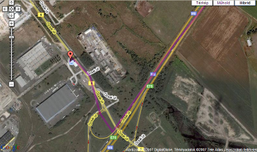
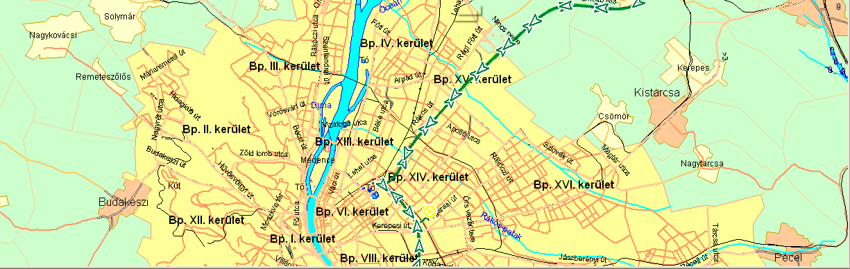
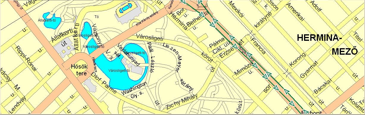
14.4.4.2. Map display
For displaying the vehicles geographical data (actual position and route history) a digital map database and map display engine (collectively referred to as Geographical Information System – GIS) is needed.
The map database stores objects such as roads, lanes, elevation etc. and geocoding information to determine the country, the settlement and the street with the house number.
Basically there are two methods used to store mapping references in a GIS database and to display the map: raster images and vector. The latter technology used geometrical primitives such as points, lines, curves, and shapes or polygons based on mathematical expressions to represent the map objects and support the generation of the map image. Contrary to the raster (or bitmap) image it provides the ability of the clear magnification.
There are several companies offer GIS solutions, technologies and services such as ESRI, Autodesk, ERDAS, MapInfo, Bentley Systems, Intergraph etc.
There are several web mapping systems also available for the internet users and more of them provide an API to support the usage in map-based web services. In recent years these services began to gain ground in Fleet Management Systems, because they offers cost-effective licenses, free development platforms and continuously expanding feature list. The most popular services are Google Maps, OpenStreetMap and Bing Maps.