Chapter 4. Human-Machine Interface
The Human-Machine Interfaces specifies the bidirectional connection from the driver to the vehicle. Designing a good HMI device is a challenging engineering task. Creation of a well-operable, user-friendly and ergonomic interface presumes great expertise.
In this Chapter the requirements of automotive HMIs, the classification and its technologies are detailed.
4.1. Requirements
The general requirements of the automotive HMIs can be summarized as follows. The HMI should inform and support the intervention considering the following aspects:
-
Readability
-
Clarity
-
Interpretability
-
Accessibility
-
Ease of handling
The above mentioned requirements aim to increase the traffic safety. All of these points serve that the handling of the vehicle should not distract the driver.
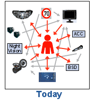
Today, a wide range of new in-vehicle technologies exist, which are introduced in this lecture, such as Advanced Driver Assistance Systems (ADAS) and In-vehicle Information Systems (IVIS). Moreover, the number of in-vehicle use of portable computing devices is increasing rapidly. These new technologies have great potential for enhancing road safety, as well as enhancing the quality of life and work, e.g. by providing in-vehicle access to new information and communication resources. However, the safety benefits of ADAS may be significantly reduced, or even cancelled, by unexpected behavioural responses to the technologies, e.g. system over-reliance and safety margin compensation. Moreover, IVIS and portable devices may induce dangerous levels of workload and driver distraction.
These problems and challenges have called to life the AIDE (Adaptive Integrated Driver-vehicle Interface) pan-European project. The general goal of the AIDE Integrated Project is to generate the knowledge and develop methodologies and human-machine interface technologies required for safe and efficient integration of ADAS, IVIS and portable devices into the driving environment. (Source: [49])

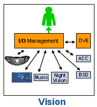
The basic theory behind AIDE can be summarized as follows. The term driver coaching involves “standard” HMI aspects and components such as visual/manual interactions with an application via a display and input controls. If a driver coaching application wants to transmit information to the driver (e.g. a pop-up message on a display), this presentation should be coordinated with other applications. If the driver is interacting with the coaching application, suppressing information from other in-vehicle applications during this interaction might be preferable. An additional possibility could be implementing the adaptivity of applications to the Driver-Vehicle-Environment (DVE) state by avoiding to provide low priority information when the driver workload is high, e.g. due to the traffic situation. (Source: [50])
As an HMI design example, in the HAVEit project, the control of the Human Machine Interface (HMI) is implemented in the command layer. The HMI control triggers the pop-ups that should be shown to the driver and decides which one to show from a prioritisation of all available pop-ups. All timing of the pop-ups is situated and parameterized in the HMI control.
4.2. HMI classifications
The automotive HMIs can be classified in several ways. Our classifications detailed in the next sections are based on the relevance, the direction (I/O) and the applied technology of the HMIs.
The direction parameter can be input or output from the drivers’ point of view. While through the input interfaces the driver can intervene into the operation of the vehicle, the output interfaces enable the indication of any vehicle parameter, thus notifying the driver about any information.
In the following subsections the relevance groups are detailed. The technical solutions are especially various and diverse, hence the authors considered the detailed explanation important. That is why the applied technologies are described in a new section.
4.2.1. Primary HMI components
The primary HMI components are used for operating the vehicle basic functions and let the driver control the movement of the vehicle. Furthermore some of these components (and the minimum set of the devices) are regulated by the legal authorities. The following primary components can be considered as a basic primary HMI set in a passenger car with manual gearbox:
-
Input devices
-
Steering wheel
-
Pedals (accelerator, brake, clutch)
-
Gear shift lever
-
Parking brake
-
Turn indicator stalk
-
Wiper stalk
-
Light switch
-
Horn
-
Output devices
-
Instrument cluster
-
Speedometer
-
Important warning lights (oil pressure, charging etc.)
-
Turn signal indicator light
-
Fuel level
4.2.1.1. Input channels
It is important to explain the evolutionary process of the steering wheel and the accelerator and brake pedals. (The clutch and gear shift evolved in another way, because of the automatic gear shift systems.) Nowadays the x-by-wire systems are increasingly coming to the fore as mentioned in the Section “Intelligent Actuators”. The necessary technical solutions are available, “only” the responsibility and legal questions are not solved yet.
With using solely x-by-wire systems in case of the primary input HMIs, the connections to the actuators are electronic signals or high-level digital messages, which determine the desired motion state of the vehicle. This digital byte stream is often referred to as motion vector. It contains the demanded values for engine torque, brake pressure and steering angle and is extended by further values like gear-shift command. With this indirect connection, the electronic control units can execute the drivers command in a more effective and safer way.
In this technical level the input devices could be any type of human interfaces, the only requirement is to generate the proper electronic output. Beyond the conventional controls, several other possibilities are available, such as a joystick that is (besides the computer games) generally used to control forklifts. Although joysticks are technically perfectly integrated control devices, these solutions are not likely to be widespread in passenger cars, because they require absolute different driving techniques. Undoubtly x-by-wire systems have got a greater importance beyond the already utilized opportunities, namely the capability to control the vehicle by a computer. As the electronic interface (motion vector) can either be generated from the human driver or from an electronic control, the intelligent actuators cannot make a difference if the request was originated from driver or a control ECU. Moreover it is one of the basis of the highly automated or fully autonomous vehicle operation.
In modern vehicles the primary controls are equipped with several sensors which could be the following:
-
Steering wheel
-
Angle
-
Force, torque
-
Touching pressure and position (for detecting the driver presence and state)
-
Driver pulse detection for medical purposes
-
Pedals
-
Position
-
Force
-
Gear shift lever
-
Reverse detection
-
Position detection
4.2.1.2. Output channels
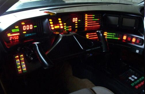
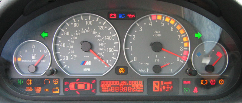
The primary HMI output is the instrument cluster. Basically it is responsible for displaying the motion state of the vehicle and the engine (such as velocity and rotational speed), feedback about the execution of the desired task (such as turn signal indicator light), and warning of the problems and errors. Additionally it could inform the driver about the detailed vehicle status, the driving situation and the current level of automation.
If we look through the evolution of the instrument cluster, it can be noticed that the development direction goes from the mechanical to the fully electronic solutions. Until the 1990s the analogue gauge of the speedometer was connected to the gearbox by a Bowden cable. Initial electric gauges used Deprez instruments, later they were driven by PWM signals using cross-coils technology. With release of the electronic motor control units, the needle of the gauge was driven by a small stepper motor which connected to the ECM. The instrument cluster has been complemented with alphanumeric and later graphical LCD displays. Nowadays the state-of-art solution is the fully colour LCD-based instrument cluster with variable style displaying. These technologies will be detailed in Section 4.3.
4.2.2. Secondary HMI components
The role of the secondary HMI components is to operate and display the comfort and infotainment functions. The controls can be found on the dashboard, around the central armrest, on the door armrest, on the steering wheel and sometimes over the central mirror. Naturally nowadays it is a very diverse and large component group. The size and content is highly dependent on the equipment features of the vehicle. Basically it contains the control inputs of the heating, ventilation, and air conditioning (HVAC) system and the radio, and some indicator lights and alphanumeric LCDs.
4.2.2.1. Input channels
The evolution of the secondary input controls is very diverse, but it has a common property at each manufacturer, namely the multiplication of the comfort and infotainment functions. It has resulted many buttons, switches, sliders and knobs all around the driver. The first solutions for the simplification were the integrated controllers with which the driver can navigate through a menu on an LCD display.
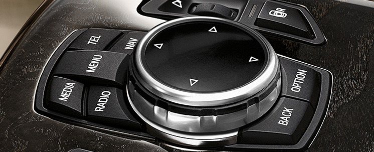
The BMW iDrive Controller was designed to be one single interface for many functions and features of the vehicle through the central console display, as replacing the array of controls of the comfort and infotainment functions with an all-in-one unit. The rotate-and-press mechanism enables one-handed operation: right means ‘continue’, left ‘back’, turning the button allows you to scroll through a list and pressing it selects an option. Frequently used functions like multimedia, radio or navigation have direct access keys. (Source: [51])
Several other methods exist to simplify the secondary input HMIs, such as steering wheel buttons and touchscreens. Generally most of these solutions are based on a menu, displayed on a relatively large screen.
The design of the secondary input devices is a more and more challenging task, because of the conflicting requirements, i.e. the increasing number of functions (especially infotainment) and the traffic safety.
4.2.2.2. Output channels
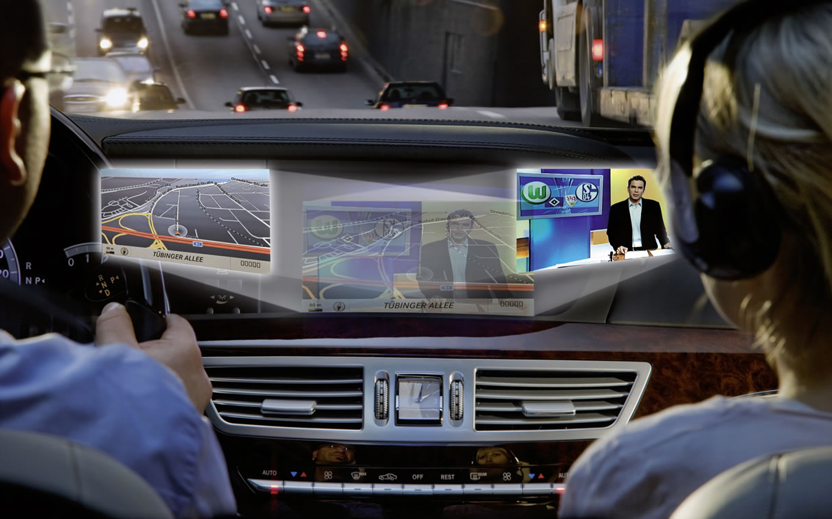
The secondary HMI output channels do not differ that much from the primary output channels, meaning that they are mostly relatively big LCD displays, but they may include special features like touch-screen control or split view of the central console, where on the same display device the driver and the “navigator” views different pictures at the same time.
4.3. HMI technologies
In the following subsections the main groups of the applied HMI technologies are detailed.
4.3.1. Mechanical interfaces
In this subsection the mechanical interfaces are introduced. We classified those technologies into this group, which require mechanical impact from the driver, which could be the following:
-
Press by hand, finger or foot
-
Pull, slide or rotate by hand
-
Touch by hand or finger
4.3.1.1. Pedal, lever
Beside the steering wheel the pedals are the basic primary inputs in an automobile. As mentioned in the earlier sections electronic throttle control solutions are commonly used in today’s road vehicles.. The driver feeling of the “traditional” accelerator pedal can be substituted with a simple spring, because it requires only a constant pressure force. Furthermore the electronic pedal gives the possibility to use haptic feedback, such as vibration or variable pedal force to support the economic driving.
In conventional passenger cars the brake pedal is connected to the brake system via a rod in the hydraulic cylinder. Brake-by-wire systems are increasingly being integrated into or replacing conventional hydraulic or pneumatic brake systems. Such electrical brake systems are preferable because they reduce the mass of the system and provide greater ability to integrate the system into the vehicle's other electronic circuits and controls. In hybrid cars it is essential because of the electronic braking by the driving motor. During depression of the brake pedal in a conventional hydraulic braking system, the hydraulic fluid will exert a force back on the brake pedal due to the hydraulic pressure in the brake lines. Since an electronic brake system may not have such hydraulic pressure at the brake pedal, the vehicle operator will not detect any countering force, which in turn can disorient the operator. Accordingly, a typical electrical brake system will include a brake pedal feel simulator to provide a simulation force on the brake pedal. The simulation force provided by the simulator acts opposite the brake pedal force generated by the vehicle driver. It has to be noted that the brake pedal simulator has to suit to the different driving situations especially during emergency. The system has to adjust automatically its operation to reduce or eliminate the simulation force during emergency or failure conditions. (Source: [52])
The clutch pedal is usually hydraulic also, and exists only in vehicles with manual gearbox. It doesn’t require such developments as mentioned above, because with the use of automatic, automated or semi-automatic gearboxes the clutch pedal itself is eliminated.
Traditionally one mechanical lever exists in vehicles, i.e. the parking brake lever. In European vehicle designs it is operated by hand (hand-brake) but in the US the parking brake is generally operated by the left foot. In modern vehicle the parking brake lever is often substituted by a push button or a fully automatic parking brake.
4.3.1.2. Steering wheel
The steer-by-wire system (mentioned in Section “Intelligent actuators”) is also an enabler of good haptic HMI systems as it provides as much design freedom as possible, because the characteristics of the steering wheel are dynamically independent from the front axle steering. For example, a vibration induced in the steering wheel for warning purposes in a mechanically decoupled steer-by-wire systems can be designed with no effect on the actual steering behaviour at the front wheels.
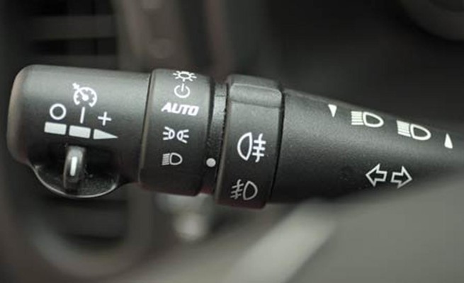
4.3.1.3. Button, switch, stalk, slider
With the help of these components the driver can activate/deactivate or set the vehicle’s primary and secondary functions. These switching components could be single buttons or switches for each function, a stalk or a slider.
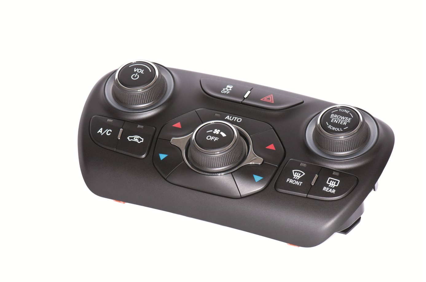
4.3.1.4. Integrated controller knob
The integrated controller knobs are such input devices which integrate more input functions into one device to support the much easier and more intuitive handling of the vehicle. These input functions could be rotation, push/pull and 4-way joystick.
A typical example is the BMW iDrive as mentioned in Section Input channels4.2.2.1, but a lot of simpler utilizations exist, such HVAC and radio control knobs.
4.3.1.5. Touchscreen
Infotainment displays often have touchscreen features enabling the driver to select functions via touching the display. Touchscreen technology is the direct manipulation type gesture based technology. A touchscreen is an electronic visual display capable of detecting and locating a touch over its display area. It is sensitive to the touch of a human finger, hand, pointed finger nail and passive objects like stylus. Users can simply move things on the screen, scroll them, zoom them and many more.
There are four main touchscreen technologies:
-
Resistive
-
Capacitive
-
Surface Acoustic Wave
-
Infrared
The most wide-spread ones are the resistive and the capacitive touchscreens, thus these types will be detailed in the following paragraphs.
Resistive LCD touchscreen monitors rely on a touch overlay, which is composed of a flexible top layer and a rigid bottom layer separated by insulating dots, attached to a touchscreen controller. The inside surface of each of the two layers is coated with a transparent metal oxide coating (ITO) that facilitates a gradient across each layer when voltage is applied. Pressing the flexible top sheet creates electrical contact between the resistive layers, producing a switch closing in the circuit. The control electronics alternate voltage between the layers and pass the resulting X and Y touch coordinates to the touchscreen controller. The touchscreen controller data is then passed on to the computer operating system for processing.
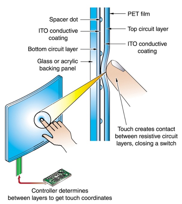
Because of its versatility and cost-effectiveness, resistive touchscreen technology is the touch technology of choice for many markets and applications. Resistive touchscreens are used in food service, retail point-of-sale (POS), medical monitoring devices, industrial process control and instrumentation, portable and handheld products. Resistive touchscreen technology possesses many advantages over other alternative touchscreen technologies (acoustic wave, capacitive, infrared). Highly durable, resistive touchscreens are less susceptible to contaminants that easily infect acoustic wave touchscreens. In addition, resistive touchscreens are less sensitive to the effects of severe scratches that would incapacitate capacitive touchscreens. Drawback can be the too soft feeling when pressing it, since there is a mechanical deformation required to connect the two resistive layers to each-other. (Source: [53])
One can use anything on a resistive touchscreen to make the touch interface work; a gloved finger, a fingernail, a stylus device – anything that creates enough pressure on the point of impact will activate the mechanism and the touch will be registered. For this reason, resistive touchscreen require slight pressure in order to register the touch, and are not always as quick to respond as capacitive touchscreens. In addition, the resistive touchscreen’s multiple layers cause the display to be less sharp, with lower contrast than we might see on capacitive screens. While most resistive screens don’t allow for multi-touch gestures such as pinch to zoom, they can register a touch by one finger when another finger is already touching a different location on the screen. (Source: [54])
The capacitive touchscreen technology is the most popular and durable touchscreen technology used all over the world. It consists of a glass panel coated with a capacitive (conductive) material Indium Tin Oxide (ITO). The capacitive systems transmit almost 90% of light from the monitor. In case of surface-capacitive screens, only one side of the insulator is coated with a conducting layer. While the screen is operational, a uniform electrostatic field is formed over the conductive layer. Whenever, a human finger touches the screen, conduction of electric charges occurs over the uncoated layer which results in the formation of a dynamic capacitor. The controller then detects the position of touch by measuring the change in capacitance at the four corners of the screen. In the projected-capacitive touchscreen technology, the conductive ITO layer is etched to form a grid of multiple horizontal and vertical electrodes. It involves sensing along both the X and Y axis using clearly etched ITO pattern. The projective screen contains a sensor at every intersection of the row and column, thereby increasing the accuracy of the system. (Source: [55])
Since capacitive screens are made of one main layer, which is constantly getting thinner as technology advances, these screens are not only more sensitive and accurate, the display itself can be much sharper. Capacitive touchscreens can also make use of multi-touch gestures, but only by using several fingers at the same time. If one finger is touching one part of the screen, it won’t be able to sense another touch accurately. (Source: [54])
4.3.2. Acoustic interfaces
The acoustic interfaces have long been common output interfaces in vehicles. They do not require that the driver take off his eyes from the road, thus it is safer than a visual output.
In the following subsections the several acoustic technologies are outlined in order of the development.
4.3.2.1. Beepers
The simple beeper was the first acoustic interfaces in automobiles, but it is still used even today. The beeper is well-suitable for warning functions. Some typical examples are given as follows:
-
Safety warnings
-
Door is open
-
Seat belt is not used
-
ADAS warnings
-
Comfort feedbacks
-
Lights left on
-
Parking assist
-
Speed limit
4.3.2.2. Voice feedback
A voice feedback capable device can provide information by human speech using speech synthesizer (text-to-speech - TTS) techniques. Speech can be created by concatenating recorded speech sections from very small units (such as phones or diphones) or entire words (sentences).
Today’s TTS systems are capable to vocalize complex texts with proper clarity. The typical fields of usage are the following:
-
Navigation systems
-
Telecommunication systems
-
Warning messages
4.3.2.3. Voice control
The voice control, unlike the previous technologies, is voice recognition-based input technique. First devices with voice control functions initially had to record each command spoken by the end-user, so voice recognition was just a comparison to the previously recorded sound data. Later voice recognition became general by providing user independent sound recognitions to a limited languages (e.g. english, german). Today the major force behind the development is the telecommunication sector, especially the smartphone, the developers of the mainstream operating systems (Android, iOS and Windows Phone).Voice control could be a useful input which could increase traffic safety by allowing the driver to issue a command without being distracted. One of the most significant players of the automotive voice control solutions is Nuance Inc. with the product called Dragon Drive . It is already used in several infotainment systems, such as Ford's Sync and GM's IntelliLink, furthermore it can be found in several BMW and Mercedes-Benz vehicles. Dragon Drive is optimized for the in-car experience with an easy-to-use natural language interface and uninterrupted delivery of all on-board and cloud content. Dragon Drive offers drivers seamless access to the content and services they want, where they want it, whether on the head unit, smartphone or on the web. (Source: [56])
Naturally Apple and Google are trying to offer their own solutions integrated into the automotive infotainment solutions, i.e. Apple CarPlay. Google has not presented a market-ready solution yet, but in January 2014 they have announced the Open Automotive Alliance, including General Motors, Honda Motor, Audi, Hyundai, and chipmaker Nvidia, that want to customize Google’s mobile operating system for vehicles.
4.3.3. Visual interfaces
4.3.3.1. Analogue gauge
The oldest and most conventional instrument device is the analogue gauge. Originally the needle of the gauge was linked with a Bowden cable to the measured unit (e.g. gearbox), later it was substituted with an electronic connection and the needle which is a proven solution today. In this case the needle is driven by magnetic field or a small electronic stepper motor.
In the newest LCD-based instrument clusters the analogue gauge type displaying will continue to be available as detailed in the following subsection.
4.3.3.2. LCD display
Liquid crystals were first discovered in the late 19th century by the Austrian botanist, Friedrich Reinitzer, and the term liquid crystal itself was coined shortly afterwards by German physicist, Otto Lehmann. The major (from automotive perspective) LCD technologies are shortly detailed in the followings based on [57].
Liquid crystals are almost transparent substances, exhibiting the properties of both solid and liquid matter. Light passing through liquid crystals follows the alignment of the molecules that make them up – a property of solid matter. In the 1960s it was discovered that charging liquid crystals with electricity changed their molecular alignment, and consequently the way light passed through them; a property of liquids.
LCD is described as a transmissive technology because the display works by letting varying amounts of a fixed-intensity white backlight through an active filter. The red, green and blue elements of a pixel are achieved through simple filtering of the white light.
Most liquid crystals are organic compounds consisting of long rod-like molecules which, in their natural state, arrange themselves with their long axes roughly parallel. It is possible to precisely control the alignment of these molecules by flowing the liquid crystal along a finely grooved surface. The alignment of the molecules follows the grooves, so if the grooves are exactly parallel, then the alignment of the molecules also becomes exactly parallel.
In their natural state, LCD molecules are arranged in a loosely ordered fashion with their long axes parallel. However, when they come into contact with a grooved surface in a fixed direction, they line up in parallel along the grooves.
The first principle of an LCD consists of sandwiching liquid crystals between two finely grooved surfaces, where the grooves on one surface are perpendicular (at 90 degrees) to the grooves on the other. If the molecules at one surface are aligned north to south, and the molecules on the other are aligned east to west, then those in-between are forced into a twisted state of 90 degrees. Light follows the alignment of the molecules, and therefore is also twisted through 90 degrees as it passes through the liquid crystals. However, when a voltage is applied to the liquid crystal, the molecules rearrange themselves vertically, allowing light to pass through untwisted.
The second principle of an LCD relies on the properties of polarising filters and light itself. Natural light waves are orientated at random angles. A polarising filter is simply a set of incredibly fine parallel lines. These lines act like a net, blocking all light waves apart from those (coincidentally) orientated parallel to the lines. A second polarising filter with lines arranged perpendicular (at 90 degrees) to the first would therefore totally block this already polarised light. Light would only pass through the second polariser if its lines were exactly parallel with the first, or if the light itself had been twisted to match the second polariser.
A typical twisted nematic (TN) liquid crystal display consists of two polarising filters with their lines arranged perpendicular (at 90 degrees) to each other, which, as described above, would block all light trying to pass through. But in-between these polarisers are the twisted liquid crystals. Therefore light is polarised by the first filter, twisted through 90 degrees by the liquid crystals, finally allowing it to completely pass through the second polarising filter. However, when an electrical voltage is applied across the liquid crystal, the molecules realign vertically, allowing the light to pass through untwisted but to be blocked by the second polariser. Consequently, no voltage equals light passing through, while applied voltage equals no light emerging at the other end.
Basically two LCD control technique exist: passive matrix and active matrix. The earliest laptops (until the mid-1990s) were equipped with monochrome passive-matrix LCDs, later the colour active-matrix became standard on all laptops. Passive-matrix LCDs are still used today for less demanding applications. In particular this technology is used on portable devices where less information content needs to be displayed, lowest power consumption (no backlight) and low cost are desired, and/or readability in direct sunlight is needed.
The most common type of active matrix LCDs (AMLCDs) is the Thin Film Transistor LCD (TFT LCD), which contains, besides the polarizing sheets and cells of liquid crystal, a matrix of thin-film transistors. In a TFT screen a matrix of transistors is connected to the LCD panel – one transistor for each colour (RGB) of each pixel. These transistors drive the pixels, eliminating at a stroke the problems of ghosting and slow response speed that afflict non-TFT LCDs.
The liquid crystal elements of each pixel are arranged so that in their normal state (with no voltage applied) the light coming through the passive filter is polarised so as to pass through the screen. When a voltage is applied across the liquid crystal elements they twist by up to ninety degrees in proportion to the voltage, changing their polarisation and thereby blocking the light’s path. The transistors control the degree of twist and hence the intensity of the red, green and blue elements of each pixel forming the image on the display.
TFT screens can be made much thinner than LCDs, making them lighter, and refresh rates reached the fast 5 ms value.
There are several TFT panel types exist considering the backlight and panel technology.
The LCDs does not produce light itself, thus a proper light source is needed to built-in to produce a visible image. (However low-cost monochrome LCDs are available without backlight.) Until about 2010 the backlight of large LCD panels was based on Cold Cathode Fluorescent Lamps (CCFLs). It has several disadvantages such as higher voltage and power needed, thicker panel design, no high-speed switching, faster aging. The new LED-based backlight technologies eliminated these harmful properties and took over the CCFL.
The panel technologies can be divided into three main groups:
-
Twisted Nematic (TN)
-
In Plane Switching (IPS)
-
VA (Vertical Alignment)
Without going into the technical details of these technologies the main comparable features are given as follows.
The TN panel provides the shortest response time (>1ms), and it is very cost effective technology. On the other hand these panels use only 18 bit colour depth which can be increased virtually, but the colour reproduction is not perfect anyway. Another disadvantage is the poor viewing angle.
The IPS panels’ core strength are the exact colour reproduction and the wide viewing angle. The response time is higher than the TN, but it managed to the proper level (>5ms) by now. Despite the higher costs, all in all the IPS panels is the best TFT LCD panels now.
Considering the properties the VA panels can be located between TN and IPS ones. Considering the contrast ratio it is the best technology, but with higher response time (>8ms) and a medium colour reproduction.
4.3.3.3. OLED display
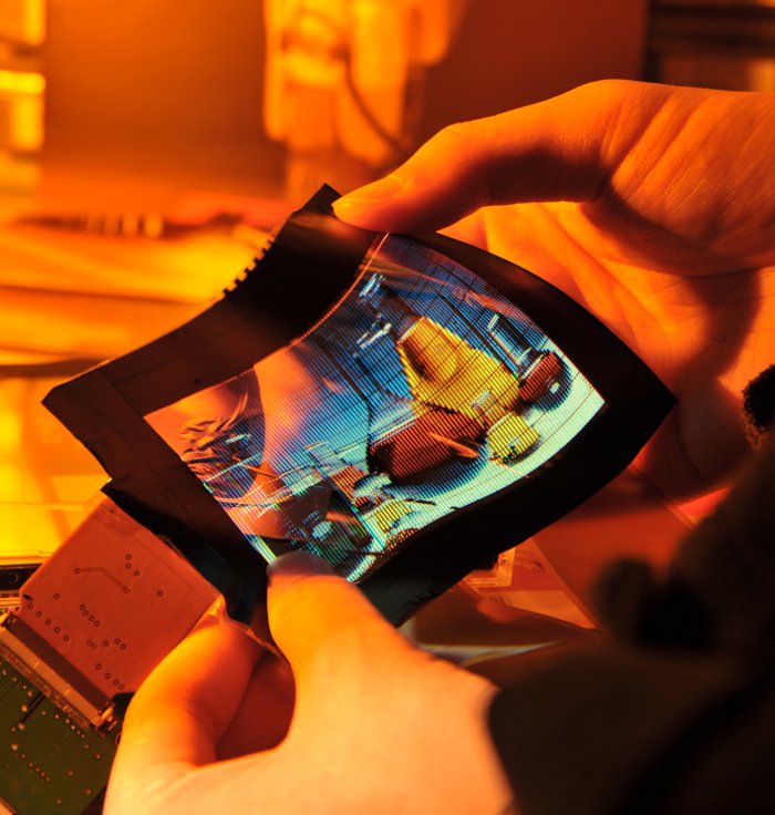
Today’s cutting-edge display technology is the OLED (organic light emitting diode). It is a flat light emitting technology, made by placing a series of organic (carbon based) thin films between two conductors. When electrical current is applied, a bright light is emitted. OLEDs can be used to make displays and lighting. Because OLEDs emit light, they do not require a backlight and so are thinner and more efficient than LCD displays. OLEDs are not just thin and efficient - they can also be made flexible (even rollable) and transparent.
The basic structure of an OLED is a cathode (which injects electrons), an emissive layer and an anode (which removes electrons). Modern OLED devices use many more layers in order to make them more efficient, but the basic functionality remains the same.
OLED displays have the following advantages over LCD displays:
-
Lower power consumption
-
Faster refresh rate and better contrast
-
Greater brightness and fuller viewing angle
-
Exciting displays (such as ultra-thin, flexible or transparent displays)
-
Better durability (OLEDs are very durable and can operate in a broader temperature range)
-
Lighter weight (the screen can be made very thin)
But OLEDs also have some disadvantages. First of all, today it costs more to produce an OLED than it does to produce an LCD. Although this should hopefully change in the future, as OLEDs has a potential to be even cheaper than LCDs because of their simple design.
OLEDs have limited lifetime (like any display, really), that was quite a problem a few years ago. But there has been constant progress, and today this is almost a non-issue. Today OLEDs last long enough to be used in mobile devices and TVs, but the lifetime of a vehicle is significantly longer. OLEDs can also be problematic in direct sunlight, because of their emissive nature, which also could be a problem in a car. But companies are working to make it better, and newer mobile device displays are quite good in that respect.
Today OLED displays are used mainly in small (2" to 5") displays for mobile devices such as phones, cameras and MP3 players. OLED displays carry a price premium over LCDs, but offer brighter pictures and better power efficiency. Making larger OLEDs is possible, but difficult and expensive now. In 2014 several new OLED TVs has been announced and presented, which shows that the manufacturers are trying to force this promising technology, which will make the lower costs in the future. (Source: [58])
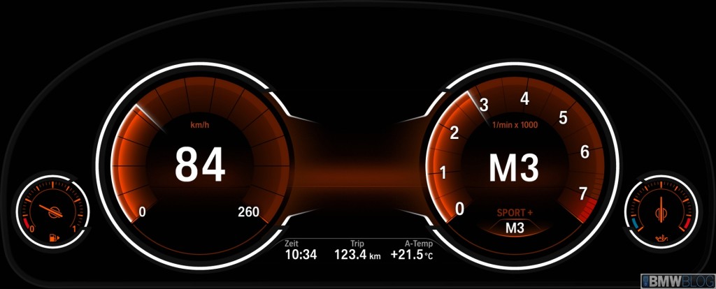
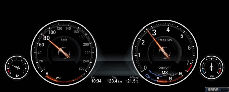
A software configurable instrument cluster is essentially an LCD display behind the steering wheel, which can be customized to different applications (e.g. sport, luxury sedan display or special diagnostic display). There is theme selection with several colour and shape configurations and we can also decide what gauges or windows should appear. Font size altering option could help for the visually impaired. The central console display can also be temporarily ported over to the instrument cluster showing radio channel information or the current image of the parking systems status. The advantage is that the driver does not have to look aside from the instrument panel
Figure 73 shows a BMW instrument panel, which is based on a 10,2”, high-resolution (318 dpi) LED LCD display, with 6:1 aspect ratio.
4.3.3.4. Head-Up Display (HUD)
As the name of the display describes the driver can keep his head straight ahead (Head-Up) while looking at displayed information projected onto the windscreen. The driver is able to check e.g. car speed without having to take his eyes off the road. The HUD earlier was used only on cockpits of fighter aircrafts, but today more and more passenger cars took over the technology.
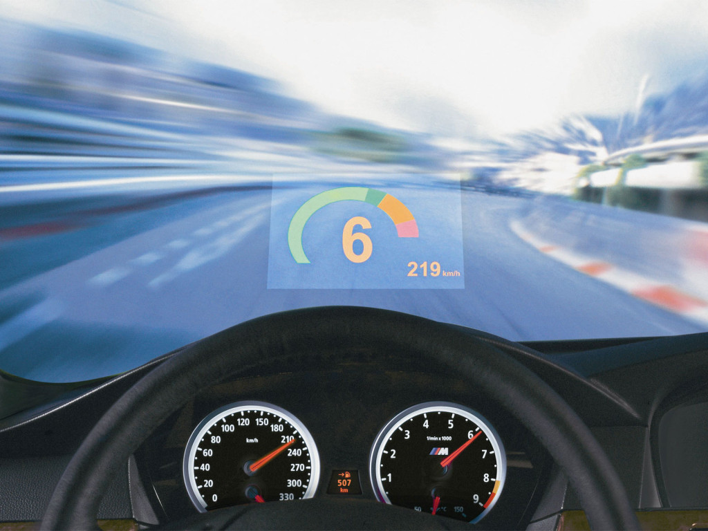
HUD system contains a projector and a system of mirrors that beams an easy-to-read, high-contrast image onto a translucent film on the windscreen, directly in your line of sight. The image is projected in such a way that it appears to be about two metres away, above the tip of the bonnet, making it particularly comfortable to read. BMW claims that Head-Up Display halves the time it takes for eyes to shift focus from road to the instruments and back. The system’s height can be adjusted for optimal viewing. The newest HUDs provides full colour displaying which makes the car even more comfortable for the driver. More colours mean it’s easier to differentiate between general driving information like speed limits and navigation directions and urgent warning signals. Important information like “Pedestrian in the road” is now even more clear and recognisable – and this subsequently reduces the driver’s reaction time. (Source [51])
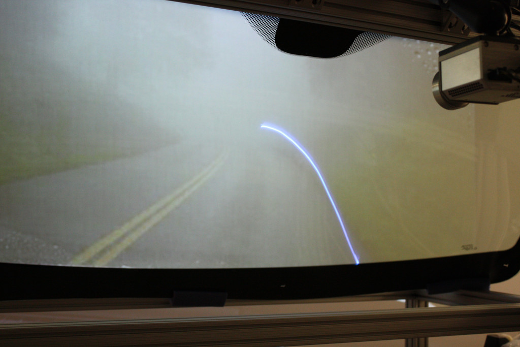
New technologies like the Head-Up Display (HUD) might be promising solution to reduce the time for the driver to be informed, because the information (road sign, speed limit, hazardous situation) can directly be projected in front of the driver eyes without any distraction. There are researches to use HUD technology on the full windshield that would revolutionize e.g. night vision applications providing road path and obstacle “simulation” feeling to driver (see Figure 75 [59]).
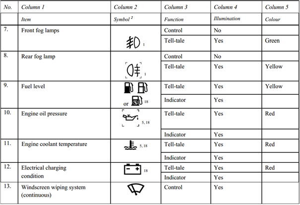
4.3.3.5. Indicator lights (Tell-tales)
Indicator lights are used in the instrument cluster to feedback of the operation of a function or indicate an error. In automotive industry the indicator lights are often called tell-tales. They could be bulbs or LEDs, which lights up a symbol or a text and the colour indicates the priority of the warning. Generally the red colour means an error that requires the car to stop immediately. In case of yellow colour the journey can be continued and it could be investigated later. But in the latter case a safety function may be out of the operation.
Indicator lights are regulated by automobile safety standards worldwide. In the United States, National Highway Traffic Safety Administration Federal Motor Vehicle Safety Standard 101 includes indicator lights in its specifications. In Europe and throughout most of the rest of the world, ECE Regulations specify it, more precisely “United Nations (UN) Vehicle Regulations - 1958 Agreement” [60].
The exact meaning and the usage of other (unregulated) symbols are manufacturer specific in the most cases.
4.3.4. Haptic interfaces
For the haptic channel, haptic feedback components on the steering wheel, the pedals and the driver’s seat are planned. The haptic functions that have already been mentioned in the corresponding sections, can be summarized as follows:
-
Pedal force and vibration for warning and efficiency functions
-
Force feedback steering wheel and vibration
-
Driver’s seat vibration for warning and safety functions
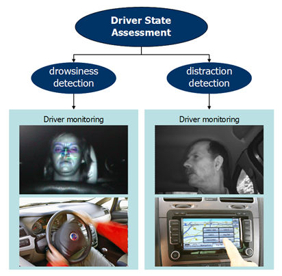
4.4. Driver State Assessment
Driver behaviour monitoring is a special category in the Human-Machine Interface section, since it does not require any direct action from the driver (e.g. pushing, touching, reading, etc.). On the other hand driver state assessment provides very important safety relevant information about the driver’s mental condition, especially drowsiness and attention/distraction which is essential in case of highly automated driving.
The risk of momentarily falling asleep during long-distance driving in the night is quite high. During driver underload situations drivers may easily loose attention, combined with monotony the risk of falling asleep even becomes higher.
Studies show that, after just four hours of non-stop driving, drivers' reaction times can be up to 50 % slower. So the risk of an accident doubles during this time. And the risk increases more than eight-fold after just six hours of non-stop driving! This is the reason why driving time recording devices (tachograph) are mandatory all across Europe for commercial vehicles. (Source: [61])
The driver status is calculated by special algorithms based on direct and indirect monitoring of the driver. The assessment of the driver can be grouped into the following categories:
-
Drowsiness level
-
Direct monitoring
-
Eye movement
-
Eye blinking time and frequency
-
Indirect monitoring
-
Driver activity
-
Lane keeping
-
Pedal positions
-
Steering wheel intensity
-
Attention/distraction level
-
Driver look focuses on the street or not
-
Use of control buttons
Direct driver status monitoring is usually based on a camera (built in the instrument panel or in the inside mirror) that records the driver face, eye movements, blinking time and frequency and determine driver status accordingly.
Indirect monitoring means the evaluation of the driver activity based on other sensor information (e.g. steering wheel movement, buttons/switches). The indirect algorithms calculate an individual behavioural pattern for the driver during the first few minutes of every trip. This pattern is then continuously compared with the current steering behaviour and the current driving situation, courtesy of the vehicle's electronic control unit. This process allows the system to detect typical indicators of drowsiness and warn the driver by emitting an audible signal and flashing up a warning message in the instrument cluster. (Source: [61])
Driver distraction is a leading cause of motor-vehicle crashes. Developing driver warning systems that measure the driver status can help to reduce distraction-related crashes. For such a system, accurately recognizing driver distraction is critical. The challenge of detecting driver distraction is to develop the algorithms suitable to identify different types of distraction. Visual distraction and cognitive distraction are two major types of distraction, which can be described as “eye-off-road” and “mind-offroad”, respectively. (Source: [62])
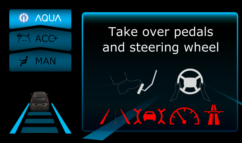
From highly automated driving point of view it is essential to know the status of the driver, whether he is able to take back control in a dangerous situation or a minimum safety risk manoeuvre has to be carried out due to medical emergency of the driver.