Chapter 5. Trajectory planning layer
The potential levels of vehicle automation are determined based on the sensor fusion information of the perception layer. Depending on the availability of the different automation levels the command layer calculates possible vehicle trajectories with priorities ranks of performance and safety. It is the task of the so called auto-pilot to calculate and rank longitudinal or combined longitudinal and lateral trajectory options. At last, taking the driver intention into account the command layer decides the level of automation and selects the trajectory to be executed.
The formulation of the vehicle trajectory, the roadpath that the vehicle travels is composed of two tasks: the trajectory planning and the trajectory execution. Trajectory planning part involves the calculation of different route possibilities with respect to the surrounding environment, contains the ranking, prioritization of the different route options based on minimizing the risk of a collision, and ends up in the selection of the optimum trajectory. The trajectory execution part contains the trajectory segmentation and the generation of the motion vector containing longitudinal and lateral control commands that will be carried out by the intelligent actuators (Section 7) of the execution layer (Section 6).
There are already vehicle automation functions available in series production (e.g. intelligent parking assistance systems) that use trajectory planning and execution. These systems are able to park the car under predefined circumstances without any driver intervention, but there are significant limitations compared to the highly automated driving. The most important difference is that parking assistance systems operate in a static or quasi-static environment around zero velocity, while for example temporary auto-pilot drives the vehicle highly automated around 130 km/h in a continuously and rapidly changing environment.
The output of this layer is a trajectory represented in the motion vector that specifies the vehicle status (position, heading and speed) for the subsequent moments.
5.1. Longitudinal motion
Longitudinal motion control has developed considerably since the beginnings. Started with standard mechanical, later electronic cruise control, passing through the radar extended adaptive cruise control, later including Stop&Go function and arriving at the V2V based cooperative adaptive cruise control system.
Early Cruise Control (CC) functions were only able to maintain a certain engine revolution at the beginning; later systems were capable of holding a predefined speed constantly. This involved longitudinal speed control by using the engine as the only actuator. The extension of the cruise control system with a long range RADAR (Section 3.1) led to the invention of the Adaptive Cruise Control (ACC) system. ACC systems (besides longitudinal speed control) could also keep a speed dependant safe distance behind the ego vehicle. Changing between speed and distance control was automatic based on the traffic situation in front of the vehicle. ACC began to use the brake system as a second actuator. With Stop & Go function, the applicability of ACC was expanded for high-congestion, stop-and-go traffic. ACC with Stop & Go can control longitudinal speed downto zero and back to set speed permitting efficient use in traffic jams. Today’s most advanced ACC systems also take into consideration topographic information from the eHorizon like the curves and slopes ahead to calculate an optimum speed profile for the next few kilometres, see Section 6.1 for details.
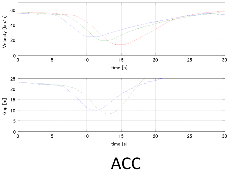
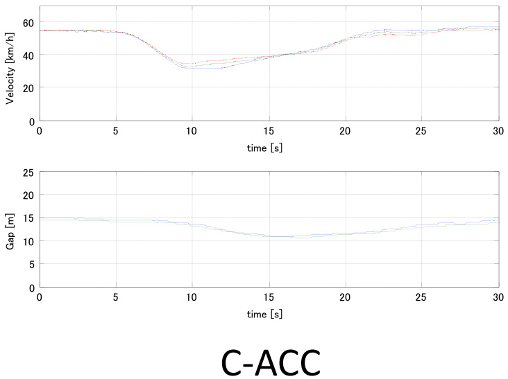
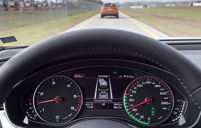
In contrast to standard adaptive cruise control (ACC) that uses vehicle mounted radar sensors to detect the distance and the speed of the ego vehicle, Cooperative ACC uses V2V communication for transmitting acceleration data to reduce the time delay of onboard ranging sensors. This enables the following vehicles to adjust their speeds according to the ego vehicle resulting in better distance keeping performance. Figure 78 shows two comparison diagrams for ACC and cooperative ACC, indicating that V2V information exchange instead of external sensor measurement can significantly reduce of the control loop. (Source: [63], [64])
5.2. Lateral motion
Lateral motion control without longitudinal motion control hardly exists, the rare example may be the assisted parking, where the lateral motion control is automated while the longitudinal motion control still remains at the driver.
The objective of assisted parking systems is to improve comfort and safety of driving during parking manoeuvres. Improve comfort by being able to park the vehicle without the driver steering and improve safety by calculating precisely the parking space size and collision-free motion trajectory avoiding any human failures that may occur during a parking manoeuvre. Series production assisted parking systems appeared on the market in the beginning of the 2000s. The advances in electronic technology enabled the development of precise ultrasonic sensors (Section 3.2) for nearby distance measurement and electronic power assisted steering (EPAS, Section 7.3) for driverless steering of the vehicle.
The task of trajectory planning starts with the determination of the proper parking space. By travelling low speed and continuously measuring the vehicle side distance, the parking gap can be calculated, thus proper parking space can be selected. As the first automated parking systems were capable of handling only parallel parking, the initial formulas for trajectory calculation were divided into the following segments:
-
straight backward path
-
full (right) steering backward path
-
straight backward path
-
full (left) steering backward path
-
(optional straight forward path)
Depending on the availability of the intelligent actuators in the vehicle the execution of the parking trajectory may also require assisted driver intervention. (Source: [65])
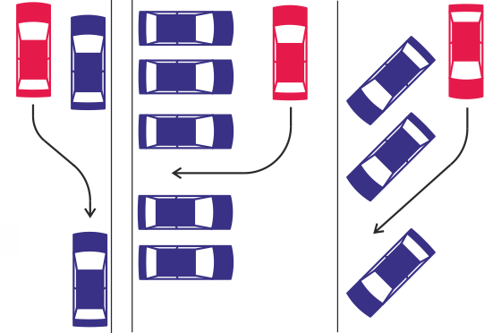
As there are different scenarios exist in everyday parking situations automated parking systems also try to assist the drivers in other situations then just parallel parking. Today’s advanced parking assist systems can also cope with perpendicular or angle parking that require a slightly different approach in lateral motion control.
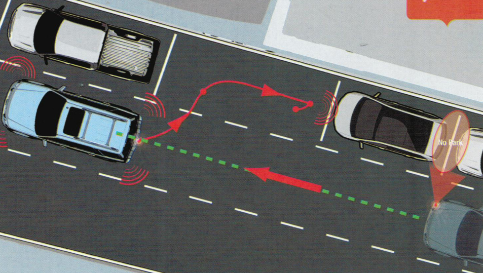
One topic of recent research in highly automated driving, which is especially challenging in urban environments is fully autonomous parking control. The challenge hereby arises from the narrow corridors, tight turns and unpredictable moving obstacles as well as multiple driving direction switching. The following figure shows common parking spots in urban environments that is subject of the research and development today. (Source: [66])
Besides parking another good example of low speed combined longitudinal and lateral control is the traffic jam assist system. At speeds between zero and 40 or 60 km/h (depending on OEMs), the traffic jam assist system keeps pace with the traffic flow and helps to steer the car within certain constraints. It also accelerates and brakes autonomously. The system is based on the functionality of the adaptive cruise control with stop & go, extended by adding the lateral control of steering and lane guidance. The function is based on the built-in radar sensors, a wide-angle video camera and the ultrasonic sensors of the parking system. As drivers spend a great amount of their time in heavy traffic, such systems could reduce the risk of rear-end collisions and protect the drivers mentally by relieving them from stressful driving. (Source: [67])
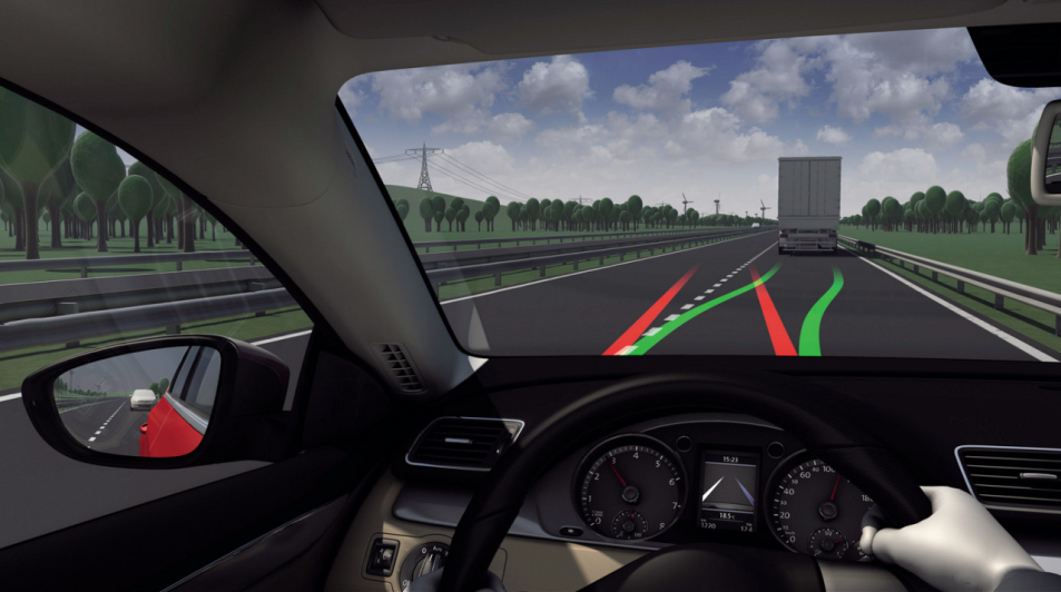
Today’s lane keeping assist (LKA) systems are the initial signs of higher speed lateral control of vehicles. Based on camera and radar information these systems are capable of sensing if the vehicle is deviating from its lane, then they help the vehicle stay inside the lane by an automated steering and/or braking intervention. An advanced extension of LKA is lane centring assist (LCA) when the vehicle not only stays inside the lane but lateral control algorithm keeps the vehicle on a path near the centre of the lane. The primary objective of the lane keeping assist and lane centring assist functions are to warn and assist the driver and these systems are definitely not designed to substitute the driver for steering the vehicle, although on technical level they would be able to do so. (Source: [68], [69])
Complex functions like highly automated driving with combined longitudinal and lateral control will definitely appear first on highways, since traffic is more predictable and relatively safe there (one-way traffic only, quality road with relative wide lanes, side protections, good visible lane markings, no pedestrians or cyclists, etc.). As highways are the best places to introduce hands-free driving at higher speeds, one could expect a production vehicle equipped with a temporary autopilot or in other words automated highway driving assist function as soon as the end of this decade.
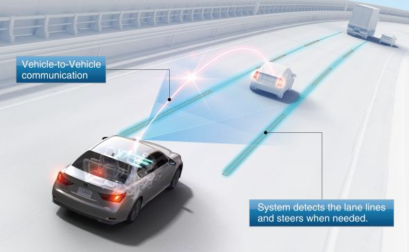
Automated highway driving means the automated control of the complex driving tasks of highway driving, like driving at a safe speed selected by the driver, changing lanes or overtaking front vehicles depending on the traffic circumstances, automatically reducing speed as necessary or stopping the vehicle in the right most lane in case of an emergency. Japanese Toyota Motor have already demonstrated their advanced highway driving support system prototype in real traffic operation. The two vehicles (shown on Figure 83) communicate each other, keeping their lane and following the preceding vehicle to maintain a safety distance. (Source: [70])
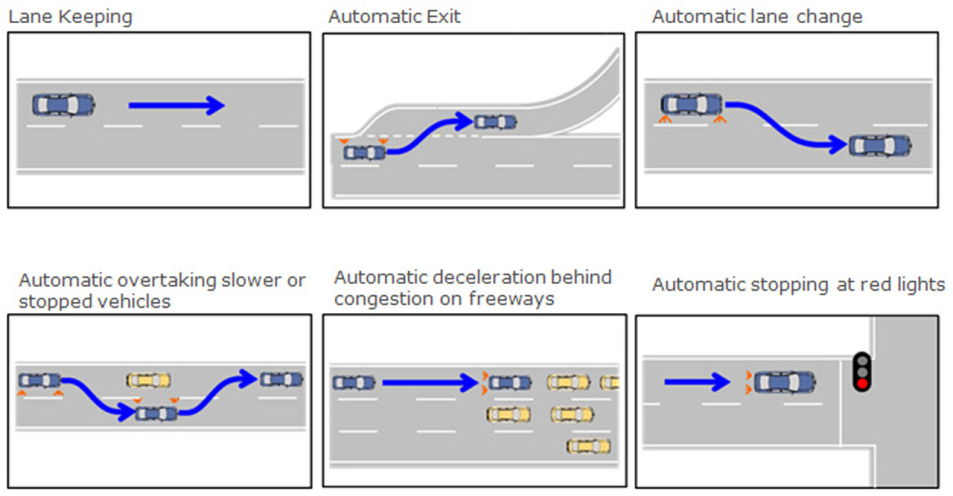
Nissan had also announced that they are also developing their highly automated cars, which is targeted to hit the road by 2020. Equipped with laser scanners, around view monitor cameras, and advanced artificial intelligence and actuators, is not fully autonomous as its systems are designed to allow the driver to manually take over control at any time. As Figure 84 illustrates the highly automated Leaf is being tested in a number of combined longitudinal and lateral control scenarios including automated highway exit, lane change, overtaking vehicles. (Source: [71]
5.3. Automation level
In highly automated vehicles it is always the driver’s decision to pass over control to the vehicle, but to be able to do so certain conditions must be met before. The trajectory planning layer processes vehicle and environment data passed on from the environment sensing (perception) layer as well as the driver's intention, the driver state assessment data and the driver automation level request which is provided by the human machine interface. The driver request for a higher automation can only be fulfilled if the prerequisites are met:
-
Availability of a higher automation level
-
Real-time environment sensing
-
Current status of vehicle dynamics
-
Driver attention
-
Driver request for higher automation
The potential automation levels provide only options for the driver requested automation levels. The command layer determines the potential automation levels and enables the system to initiate transitions between different levels based on the driver’s decision.
5.4. Auto-pilot
There is an auto-pilot algorithm responsible for the calculation of potential trajectory and for the selection of the optimum path. The algorithm processes the current situation of the vehicle, the output of the environment sensing (front vehicle, objects, lanes, road, intersection information, etc.) and the intention of the driver (by means of automation level). Finally the auto-pilot system generates the motion vector that will be carried out by the vehicle powertrain controllers and intelligent actuators in order to execute the computed path.
From the results of the multi-sensor based fusion module, the co-pilot algorithms will identify the type of situation the vehicle is in and generate driving strategy options to handle the situation. Driving strategy in this context means a set of feasible manoeuvres and trajectories to be realized by the vehicle or the driver. Driving strategy determination is based upon the analysis of the current driving situation (based on both environment sensor information and future estimation). The assessment of the danger level of the current driving situation may lead the system to select a minimum safety risk strategy or an emergency strategy for the sake of safety. The objective of the auto-pilot is to determine the optimum driving strategy for the driving context.
The co-pilot will provide the set of trajectories with their prioritization. Furthermore, a description of the manoeuvres which the automation intends to perform is provided by these trajectories. Every trajectory is assigned to a specific manoeuvre (e.g. slow down and stop; slow down and steer right; speed up, steer left and overtake) and vice versa. The calculations are based on the input from the perception layer. Irrespective of the automation level, the auto-pilot process is divided into two main functions (Source: [6]):
-
The definition of a driving strategy at a high level, which is described using a manoeuvre language.
-
The definition of trajectory at a lower level: this function uses the previously selected manoeuvre to define a reduced possibility field of the trajectory.
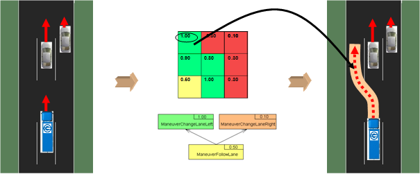
The definition of a driving strategy at a high level sub module is based on fast and simple algorithms that evaluate the possibility of several predefined manoeuvres. Some examples of these manoeuvres are “stay in the same lane and accelerate” and “change to the right lane and brake”. Each manoeuvre is ranked by a performance indicator. The aim of this high level is to quickly eliminate a part of the search space, thus reducing the calculation time of the definition of trajectory at low level. It also allows a high level communication towards the driver, in the form of a manoeuvre grid or a manoeuvre tree. There are two ways to represent these manoeuvres: the grid which is a 3x3 matrix, giving 9 cases for the 9 basic manoeuvres plus 1 case for the emergency brake manoeuvre and 1 for the minimum safety risk manoeuvre. Each case is coloured according to its performance indicator (red to orange to yellow to green). The tree representation gives the current situation, and it visualizes the possible actions with their performance indicator as the branches of this tree.
The “definition of trajectory” sub-module describes and evaluates the manoeuvres proposed by the “definition of driving strategy” sub module in greater detail, choosing the best manoeuvres first, until a predefined calculation time span (which is linked to a safe reaction time) elapses.
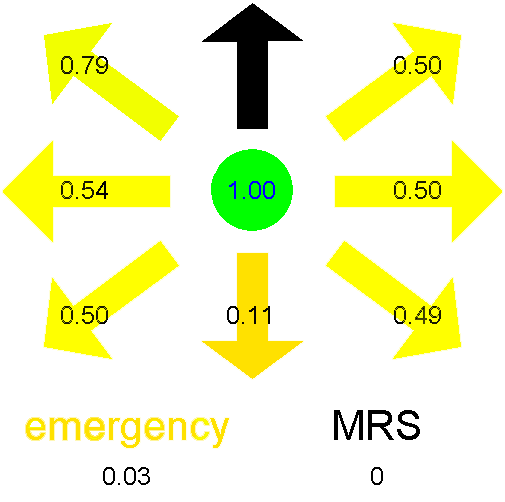
The manoeuvre grid contains the potential longitudinal and lateral actions that the vehicle is capable of performing in its current position. The output of this grid is a ranking of the manoeuvres. The calculation takes into consideration 9 possible combinations that comprise of the multiplication of the 3 longitudinal and 3 lateral options. In the longitudinal direction, the vehicle can accelerate, decelerate (brake) or can keep the current velocity, while in the lateral direction, the vehicle can change lane either to the left or to the right, or can stay in the current lane. There are two additional manoeuvres that have to be considered during the potential manoeuvre calculation, the minimum safety risk manoeuvre and the emergency manoeuvre with maximum braking till standstill. This gives a total of eleven manoeuvres. Each manoeuvre gets a performance indication number between zero and one.
When there are several potential vehicle trajectories available that do not contain the risk of a collision, then the next task is a more detailed evaluation to select the optimum trajectory from them. For being able to select the optimum path, the potential trajectories are ranked and optimized through qualitative and quantitative evaluation according to key performance indicators like:
-
trajectory complexity
-
travelling time
-
driving comfort
-
fuel consumption
-
safety margins
The manoeuvre grid algorithm attributes a performance to each of the presented manoeuvres. This is done through the evaluation of a set of performance indicators that are linked with the aspects of good driving. The algorithm measures the risk of collisions with other objects if the manoeuvre would be executed. The total performance of each manoeuvre is the weighted sum of the different performance indicators. Manoeuvres that correspond to a fast and smooth drive without risk or offence against the traffic rules are promoted in the ranking of the manoeuvre grid. The overall weighted performance indicator is presented above; it is used by the manoeuvre fusion algorithm.
According to the assumed driving situation on Figure 86, the best manoeuvre - taking into consideration the trajectory ratings of the grid and tree performance indicators- is overtaking and acceleration in the left lane.
5.5. Motion vector generation
At the end of the trajectory planning the motion control vector is generated based on the output of the environment sensing layer, the auto-pilot and the automation mode selector. The motion control vector contains the desired longitudinal and lateral control demands (and constraints) to be executed by the vehicle. As an interface vector it is passed on to the execution layer and will be executed by the powertrain controllers and the intelligent actuators.