Chapter 11. Different methods for platooning control
The number of persons and volume of goods transported on the roads have increased significantly. Simultaneously, requirements have also increased. Here are some examples: a need to enhance passenger comfort, to improve road holding, the efficiency of transport, the safety of travel, the reliability of vehicle components and also to reduce fuel consumption and the time transport takes, etc. The vehicle industry primarily focuses on the re-design of vehicle components or the efficiency of different vehicle functions. In this sense the application of active components with high versatility has great potential.
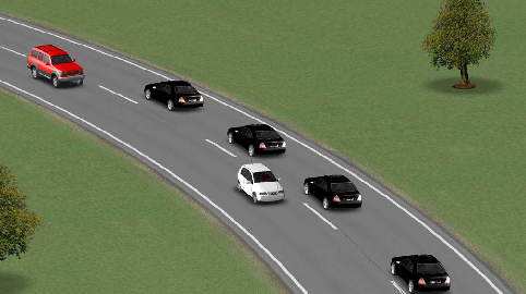
Another direction addresses the joint control of vehicle groups. The term platoon is used to describe several vehicles operated under automatic control as a unit when they are traveling at the same speed with relatively small inter-vehicle spacings. According to the principle of the platoon, the first vehicle is driven by a professional driver, while the following vehicles are under automated longitudinal and lateral control and these drivers are able to undertake other tasks. The following vehicle driver must be able to take over control of the vehicle in the event of a controlled or unforeseen dissolving of the platoon. A well-organized platoon control may have advantages in terms of increasing highway capacity and decreasing fuel consumption and emissions.
The thoughts of platoon control were motivated by intelligent highway systems and road infrastructure, see the PATH program in California and the MOC-ITS program in Japan. The European programmes were based on the existing road networks and infrastructure and focused mainly on commercial vehicles with their existing sensors and actuators, see [123], [124], [125]. The main goal of the projects was to examine the operation of platoons on public motorways with full interaction with other vehicles. In a Hungarian project an automated vehicle platoon of heavy vehicles was developed. The goal of the project was to analyze the control algorithms and synthesize the experimental results, see [126].
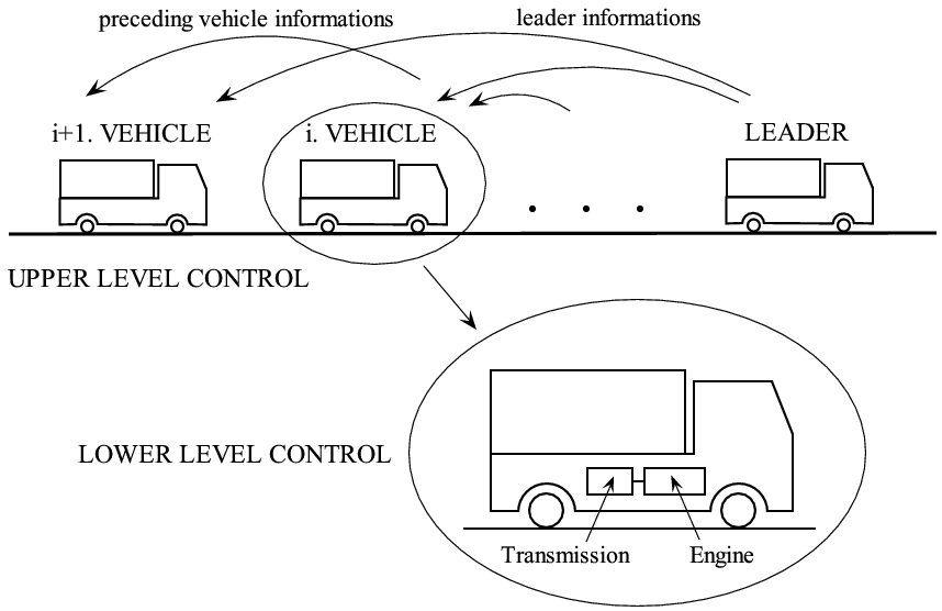
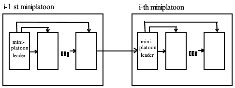
The control design is based on external factors such as traffic situations (traffic jam), terrain characteristics (straight, road slopes), road types (highway, secondary road), speed limits. It is also based on different internal factors such as the dynamic abilities of vehicles in the platoon, their emission properties, reliability. Since the safe and economical motion of the platoon is determined by the leader vehicle, it is crucial for the leader vehicle to use this piece of information during the journey. The schematic structure of the controlled platoon system is shown in Figure 144.
11.1. Control tasks
The vehicle following control law is said to provide individual vehicle stability if the spacing error of the vehicles converges to zero when the preceding vehicle is operating at constant speed. If the preceding vehicle is accelerating or decelerating, then the spacing error is expected to be nonzero. Spacing error in this definition refers to the difference between the actual spacing from the preceding vehicle and the desired inter-vehicle spacing.
Let  be the location of the
  vehicle measured from an inertial reference, see Figure 145.
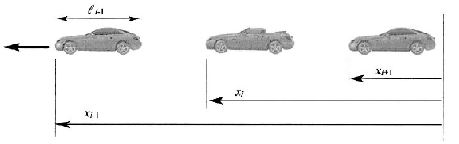
The spacing error for the  vehicle is then defined as
|
|
(1) |
where  is the desired spacing and includes the preceding vehicle length. The desired spacing
  must be chosen as a function of variables such as the vehicle speed
  . The control law is said to provide individual vehicle stability if the following condition is satisfied
|
|
(2) |
If the vehicle following control law ensures individual vehicle stability, the spacing error should converge to zero when the preceding vehicle moves at constant speed. However, the spacing error is expected to be non-zero during acceleration or deceleration of the preceding vehicle. It is important then to describe how the spacing error would propagate from vehicle to vehicle in a string of ACC vehicles that use the same spacing policy and control law.
The string stability of a string of ACC vehicles refers to a property in which spacing errors are guaranteed not to amplify as they propagate towards the tail of the string, see (1), (2). For example, string stability ensures that any errors in spacing between the  and
and cars does not amplify into an extremely large spacing error between cars
  and
and  when (
 ) further up in the string of vehicles.
In order to evaluate autonomous platoons from control point of view string stability and performance are analyzed. By definition, the platoon is string stable if, for a given  , there exist
  such that
|
|
(3) |
where  and
and  . In other words the spacing errors remain bounded along the platoon whenever the initial spacing errors are bounded. It follows from the definition that the spacing errors due to changes in lead vehicle speed do not amplify along the platoon and in time when string stability is satisfied [127].
The following condition will be used to determine if the system is string stable:
|
|
(4) |

where  is the transfer function relating the spacing errors of consecutive vehicles
  .
.
Platoon performance is commonly defined as either the largest peak spacing error or the total length of the platoon. In the paper, series
|
|
(5) |
are evaluated from which both quantities can be derived. The infinity norm of a scalar signal  is defined by
  . From series
  ,
,  one can chose constant safety gaps
  and inspect the ability of the platoon to attenuate errors. Furthermore, the possibility of actuator saturation can be concluded.
Remark 1.1
It can be shown that an autonomous controller cannot ensure string stability when the constant spacing policy is used. In the constant spacing policy, the desired spacing between successive vehicles is defined by
 where
where
 is a constant and includes the length
 of the preceding vehicle. The spacing error of the i th vehicle is defined as
 . When the acceleration of the vehicle can be instantaneously controlled, then a linear control system of the type
 yields
 , which leads to the following closed-loop error dynamics
 . This equation shows the the propagation of spacing errors in the platoon of vehicles. The magnitude of the transfer function between
 and
and
 may be greater than 1 so the autonomous control law is not string stable. Thus, in the case of the constant spacing policy, string stability cannot be
ensured by autonomous control.
may be greater than 1 so the autonomous control law is not string stable. Thus, in the case of the constant spacing policy, string stability cannot be
ensured by autonomous control.
11.2. Platooning strategies
Two type os control strategies have been proposed:
-
Constant Spacing control strategies
-
Variable Spacing control strategies
In the Constant Spacing control strategies, the desired inter-vehicule spacing is independent of the velocity of the controlled vehicle. The tracking requirement is stringent, since every controlled vehicle has to match its position, velocity and acceleration with the vehicle ahead. As a consequence, these strategies require more information to guarantee performance. The achievable traffic capacity is very high in a constant spacing control strategy. There are several solutions for constant spacing strategy:
-
Control with information of reference vehicle information only
-
Control with information of preceding vehicle
-
Control with information of lead and preceding vehicles
-
Mini platoon control
In the Variable Spacing control strategies the desired inter-vehicle spacing varies with the velocity of the controlled vehicle. The tracking requirement is not as stringent as the previous case. Some of the variable spacing control strategies can be implemented with on-board sensors. A possible solution for variable spacing strategy is the
-
Autonomous
-
Intelligent Cruise Control.
In the following the main features of the most important three strategies are presented.
Case 1.1 Control with information of lead vehicle
The first method is based on the reference velocity information. Consider the following control law:
|
|
(6) |
where  is the position of the lead vehicle in the platoon.
The spacing error dynamics is obtained using the following equation:  thus
thus  . This is the best achievable platoon performance. It is unsafe since it does not take the information of the preceding vehicle into consideration.
Case 1.2 Control with information of preceding vehicle
In this strategy control law is based only on the on-board sensor measurements. The control law is the following
|
|
(7) |
and the spacing Error Dynamics is as follows:  thus
thus
|
|
(8) |
for i=1  , where
  is the acceleration of the leader. The frequency function:
|
|
(9) |
thus in the frequency domain
|
|
(10) |
Since  , the spacing amplifying along the platoon. Consequently, the string stability is not fulfilled.
Case 1.3 Control with information of lead and preceding vehicles
The control strategy is based on lead vehicle acceleration, velocity and position information:
(11)
The string stability is guaranteed. The platoon control can be distributed into two control tasks: longitudinal control for speed tracking and lateral control for trajectory tracking.
In the simulation example four vehicles are traveling along an undulating road and the controller changes the reference velocities, which are tracked by the vehicles accurately, see Figure 3(a). The control signals are the longitudinal control forces, see Figure 3(d), which are realized by the throttle positions and the brake pressures.
|
|
|
|
|
|
|
|
|
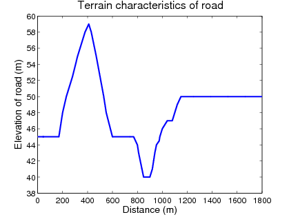
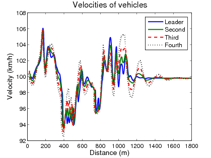
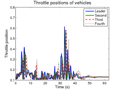
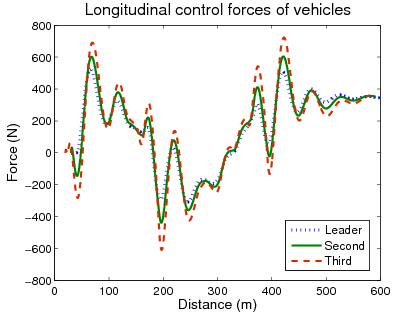
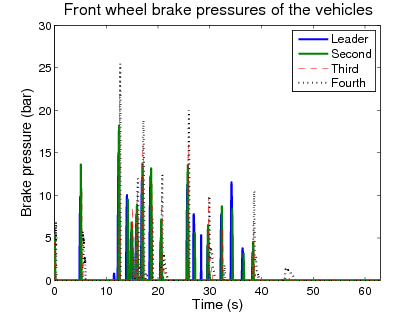
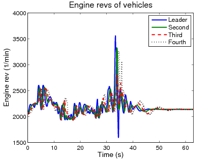
Figure 146: Simulation example
Remark 1.2 In the travelling the safety operation must be guaranteed. In the following three possible solutions for collision avoidance are presented.
-
Avoiding collision by grading vehicles: A possible way to handle saturation is to grade vehicles in the platoon in order of their dynamical ability.
-
Avoiding collision by modifying the velocity of the leader vehicle: In the strategy the communication with the leader vehicle is bidirectional. To avoid the saturation and the consequent split off of the following vehicles the velocity of the leader vehicle is moderated.
-
Avoiding collision by splitting platoon: In this lay-out the platoon dissolves into several platoons following each other, where the last vehicle of the preceding platoon serves as the reference vehicle for the following platoon.
In another example the platoon is organized with dynamically different vehicles. The leader vehicle followed the target velocity adjusted by the onboard cruise control while saturation occurred in one of the the following vehicles. Vehicles in the platoon having worse mass/performance figures are not able to match the acceleration prescribed by their controller during uphill or heavy acceleration therefore they cannot keep the desired spacing.
Because of the splitting off the following vehicle prescribes bigger acceleration than necessary (due to the growing distance from the leader vehicle), hence the following vehicle can interfere with the saturating vehicle. Figure 6 shows that because if it is notable mass, the desired force related to the prescribed acceleration is too big. Hence saturation occurs at this vehicle, consequently it cannot match the prescribed acceleration and in this manner it splits off from the platoon. The significantly big spacing error with a negative sign shows the split off. Due to this, the fifth vehicle prescribes bigger acceleration than it is necessary, hence it runs into the fourth vehicle.
|
|
|
|
|
|
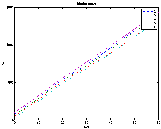
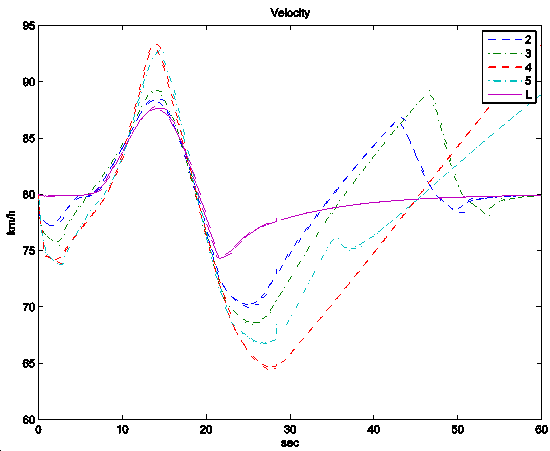
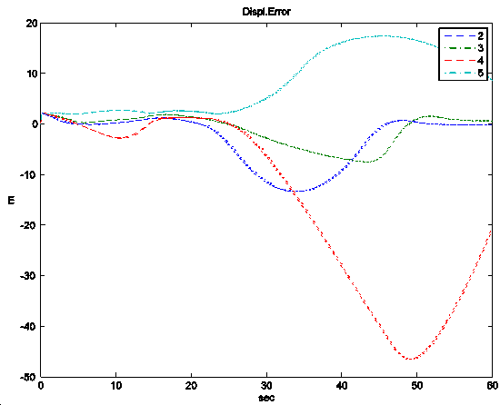
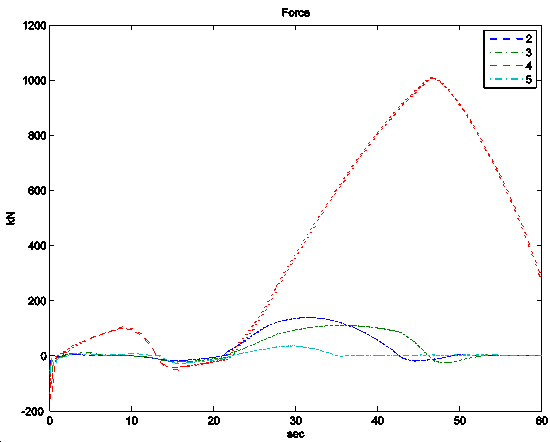
Figure 148: Simulation results with diverse vehicles